FRONT POWER SEAT CONTROL SYSTEM (w/ Memory) Power Seat Position is not Memorized
DESCRIPTION
-
for driver side
The main body ECU (multiplex network body ECU) receives seat memory switch signals from the outer mirror control ECU assembly (driver side) via CAN. If the seat memory SET switch is being pressed and the M1 switch, M2 switch or M3 switch is pressed, or if the M1switch, M2 switch or M3 switch is pressed within 3 seconds after pressing the seat memory SET switch, the main body ECU (multiplex network body ECU) sends a memory request signal to the front power seat switch (driver side). After receiving the request signal, the front power seat switch (driver side) memorizes location data of each motor.
-
for front passenger side
The front power seat switch (front passenger side) receives seat memory signals from the outer mirror control ECU assembly (front passenger side) via CAN. If the seat memory SET switch is being pressed and the M1, M2 or M3 switch is pressed, or if the M1, M2 or M3 switch is pressed within 3 seconds after pressing the seat memory SET switch, the front power seat switch (front passenger side) memorizes the position data of each motor.
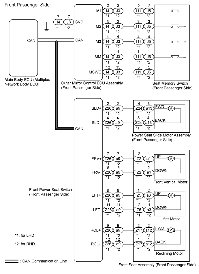
WIRING DIAGRAM

INSPECTION PROCEDURE
Note
-
The seat position will not be recorded if the SET switch and 2 or more of the seat memory switches (for example, M1 switch and M2 switch) are pressed simultaneously.
-
If a memorizing operation has failed, release all switches. The seat memory function does not operate unless the switches are released.
-
Inspect the fuses for circuits related to this system before performing the following inspection procedure.
PROCEDURE
-
CHECK CAN COMMUNICATION SYSTEM
-
Use the intelligent tester to check if the CAN communication system is functioning normally Click here.
OK CAN communication DTC is not output.
NG 
GO TO CAN COMMUNICATION SYSTEM Click here
OK 
-
-
CHECK SEAT MEMORY FUNCTION
-
Perform a memory operation properly. Check that the buzzer sounds to indicate the completion of the memory operation Click here.
Tech Tips
-
The seat position will not be recorded if the SET switch and 2 or more of the memory switches (for example, M1 and M2) are pressed simultaneously.
-
If a memorizing operation has failed, release all switches. The seat memory function does not operate unless the switches are released .
OK Seat memory switch function operates normally. Result Result Proceed to NG (Driver side seat memory function does not operate) A NG (Passenger side seat memory function does not operate) B OK C -
B 
CHECK POWER SEAT CONTROL FUNCTION Click here
C
USE SIMULATION METHOD TO CHECK Click here
A
-
-
CHECK POWER SEAT CONTROL FUNCTION
-
Check that each function of the power seat operates normally by using the front power seat switch Click here.
OK Each function of power seat operates normally by using front power seat switch.
NG
GO TO OTHER FLOW CHART (Power Seat does not Operate with Front Power Seat Switch) Click here
OK
-
-
READ VALUE USING INTELLIGENT TESTER (MIRROR)
-
Connect the intelligent tester to the DLC3.
-
Turn the power switch on (IG).
-
Turn the intelligent tester on.
-
Enter the following menus: Body / Mirror L or R / Data List.
-
Read the Data List according to the display on the intelligent tester.
Mirror L or R Tester Display Measurement Item/Range Normal Condition Diagnostic Note SET Switch SET switch signal / ON or OFF ON: SET switch on
OFF: SET switch off
- M1 Switch M1 switch signal / ON or OFF ON: M1 switch on
OFF: M1 switch off
- M2 Switch M2 switch signal / ON or OFF ON: M2 switch on
OFF: M2 switch off
- M3 Switch M3 switch signal / ON or OFF ON: M3 switch on
OFF: M3 switch off
- OK ON or OFF is displayed on the intelligent tester according to the table above.
NG
INSPECT SEAT MEMORY SWITCH (DRIVER SIDE) Click here
OK
-
-
REPLACE OUTER MIRROR CONTROL ECU ASSEMBLY (DRIVER SIDE)
-
Replace the outer mirror control ECU assembly (driver side) Click here.
NEXT
-
-
CHECK SEAT MEMORY FUNCTION (SEAT POSITION MEMORY FUNCTION)
-
Perform a memory operation properly. Check that the buzzer sounds to indicate the completion of the memory operation Click here.
Note
-
The seat position will not be recorded if the SET switch and 2 or more of the seat memory switches (for example, M1 switch and M2 switch) are pressed simultaneously.
-
If a memorizing operation has failed, release all switches. The seat memory function does not operate unless the switches are released.
OK Seat memory switch function operates normally. -
NG
REPLACE FRONT POWER SEAT SWITCH Click here
OK 
END (OUTER MIRROR CONTROL ECU ASSEMBLY (DRIVER SIDE) WAS DEFECTIVE)
-
-
REPLACE FRONT POWER SEAT SWITCH
-
Replace the front power seat switch Click here.
NEXT
-
-
CHECK SEAT MEMORY FUNCTION
-
Perform a memory operation properly. Check that the buzzer sounds to indicate the completion of the memory operation Click here.
Note
-
The seat position will not be recorded if the SET switch and 2 or more of the seat memory switches (for example, M1 switch and M2 switch) are pressed simultaneously.
-
If a memorizing operation has failed, release all switches. The seat memory function does not operate unless the switches are released.
OK Seat memory switch function operates normally. -
NG
REPLACE MAIN BODY ECU (MULTIPLEX NETWORK BODY ECU) Click here
OK
END (FRONT POWER SEAT SWITCH (DRIVER SIDE) WAS DEFECTIVE)
-
-
INSPECT SEAT MEMORY SWITCH (DRIVER SIDE)
-
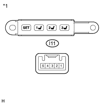
Text in Illustration *1 Component without harness connected
(Seat Memory Switch LH (Driver Side))
for LHD.
-
Remove the seat memory switch LH Click here.
-
Measure the resistance according to the value(s) in the table below.
Standard Resistance Tester Connection Switch Condition Specified Condition J5-2 - J5-5 M1 switch pressed Below 1 Ω J5-3 - J5-5 M2 switch pressed Below 1 Ω J5-4 - J5-5 M3 switch pressed Below 1 Ω J5-1 - J5-5 SET switch pressed Below 1 Ω J5-2 - J5-5 M1 switch not pressed 10 kΩ or higher J5-3 - J5-5 M2 switch not pressed 10 kΩ or higher J5-4 - J5-5 M3 switch not pressed 10 kΩ or higher J5-1 - J5-5 SET switch not pressed 10 kΩ or higher
-
-
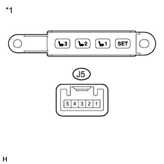
Text in Illustration *1 Component without harness connected
(Seat Memory Switch RH (Passenger Side))
for RHD.
-
Remove the seat memory switch RH Click here.
-
Measure the resistance according to the value(s) in the table below.
Standard Resistance Tester Connection Switch Condition Specified Condition I11-2 - I11-5 M1 switch pressed Below 1 Ω I11-3 - I11-5 M2 switch pressed Below 1 Ω I11-4 - I11-5 M3 switch pressed Below 1 Ω I11-1 - I11-5 SET switch pressed Below 1 Ω I11-2 - I11-5 M1 switch not pressed 10 kΩ or higher I11-3 - I11-5 M2 switch not pressed 10 kΩ or higher I11-4 - I11-5 M3 switch not pressed 10 kΩ or higher I11-1 - I11-5 SET switch not pressed 10 kΩ or higher
-
NG
REPLACE SEAT MEMORY SWITCH (DRIVER SIDE) Click here
OK
-
-
CHECK HARNESS AND CONNECTOR (OUTER MIRROR CONTROL ECU ASSEMBLY - SEAT MEMORY SWITCH)
-
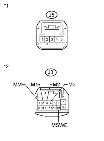
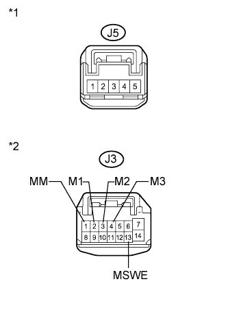
Text in Illustration *1 Front view of wire harness connector
(to Seat Memory Switch LH)
*2 Front view of wire harness connector
(to Outer Mirror Control ECU Assembly (Driver Side))
for LHD.
-
Disconnect the J3 connector from the outer mirror control ECU assembly (driver side).
-
Measure the resistance according to the value(s) in the table below.
Standard Resistance Tester Connection Condition Specified Condition J5-1 - J3-1 (MM) Always Below 1 Ω J5-2 - J3-2 (M1) Always Below 1 Ω J5-3 - J3-3 (M2) Always Below 1 Ω J5-4 - J3-4 (M3) Always Below 1 Ω J5-5 - J3-13 (MSWE) Always Below 1 Ω J3-1 (MM) - Body ground Always 10 kΩ or higher J3-2 (M1) - Body ground Always 10 kΩ or higher J3-3 (M2) - Body ground Always 10 kΩ or higher J3-4 (M3) - Body ground Always 10 kΩ or higher J3-13 (MSWE) - Body ground Always 10 kΩ or higher
-
-
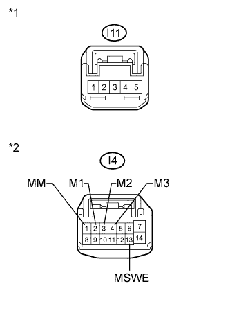
Text in Illustration *1 Front view of wire harness connector
(to Seat Memory Switch RH)
*2 Front view of wire harness connector
(to Outer Mirror Control ECU Assembly (Driver Side))
for RHD.
-
Disconnect the I4 connector from the outer mirror control ECU assembly (driver side).
-
Measure the resistance according to the value(s) in the table below.
Standard Resistance Tester Connection Condition Specified Condition I11-1 - I4-1 (MM) Always Below 1 Ω I11-2 - I4-2 (M1) Always Below 1 Ω I11-3 - I4-3 (M2) Always Below 1 Ω I11-4 - I4-4 (M3) Always Below 1 Ω I11-5 - I4-13 (MSWE) Always Below 1 Ω I4-1 (MM) - Body ground Always 10 kΩ or higher I4-2 (M1) - Body ground Always 10 kΩ or higher I4-3 (M2) - Body ground Always 10 kΩ or higher I4-4 (M3) - Body ground Always 10 kΩ or higher I4-13 (MSWE) - Body ground Always 10 kΩ or higher
-
NG
REPAIR OR REPLACE HARNESS OR CONNECTOR
OK
REPLACE FRONT POWER SEAT SWITCH (DRIVER SIDE) Click here
-
-
CHECK POWER SEAT CONTROL FUNCTION
-
Check that each function of the power seat operates normally by using the front power seat switch Click here.
OK Each function of power seat operates normally by using front power seat switch.
NG
GO TO OTHER FLOW CHART (Front Power Seat does not Operate with Front Power Seat Switch) Click here
OK
-
-
READ VALUE USING INTELLIGENT TESTER (MIRROR)
-
Connect the intelligent tester to the DLC3.
-
Turn the power switch on (IG).
-
Turn the intelligent tester on.
-
Enter the following menus: Body / Mirror L or R / Data List.
-
Read the Data List according to the display on the intelligent tester.
Mirror L or R Tester Display Measurement Item/Range Normal Condition Diagnostic Note SET Switch SET switch signal / ON or OFF ON: SET switch on
OFF: SET switch off
- M1 Switch M1 switch signal / ON or OFF ON: M1 switch on
OFF: M1 switch off
- M2 Switch M2 switch signal / ON or OFF ON: M2 switch on
OFF: M2 switch off
- M3 Switch M3 switch signal / ON or OFF ON: M3 switch on
OFF: M3 switch off
- OK ON or OFF is displayed on the intelligent tester according to the table above.
NG
READ VALUE USING INTELLIGENT TESTER Click here
OK
REPLACE FRONT POWER SEAT SWITCH Click here
-
-
READ VALUE USING INTELLIGENT TESTER
-
Enter the following menus: Body / Passenger Seat / Data List.
-
Read the Data List according to the display on the intelligent tester.
Passenger Seat Tester Display Measurement Item/Range Normal Condition Diagnostic Note Seat Memory No1 Seat position memorized with M1 switch / Mem or Not Mem Mem: Memorized
Not Mem: Not memorized
- Seat Memory No2 Seat position memorized with M2 switch / Mem or Not Mem Mem: Memorized
Not Mem: Not memorized
- Seat Memory No3 Seat position memorized with M3 switch / Mem or Not Mem Mem: Memorized
Not Mem: Not memorized
-
NG
INSPECT SEAT MEMORY SWITCH (FRONT PASSENGER SIDE) Click here
OK
-
-
REPLACE OUTER MIRROR CONTROL ECU ASSEMBLY (FRONT PASSENGER SIDE)
-
Replace the outer mirror control ECU assembly (front passenger side) Click here.
NEXT
-
-
CHECK SEAT MEMORY FUNCTION (SEAT POSITION MEMORY FUNCTION)
-
Perform a memory operation properly. Check that the buzzer sounds to indicate the completion of the memory operation Click here.
Note
-
The seat position will not be recorded if the SET switch and 2 or more of the seat memory switches (for example, M1 switch and M2 switch) are pressed simultaneously.
-
If a memorizing operation has failed, release all switches. The seat memory function does not operate unless the switches are released.
OK Seat memory switch function operates normally. -
NG
REPLACE FRONT POWER SEAT SWITCH (FRONT PASSENGER SIDE) Click here
OK
END (OUTER MIRROR CONTROL ECU ASSEMBLY (FRONT PASSENGER SIDE) WAS DEFECTIVE
-
-
INSPECT SEAT MEMORY SWITCH (FRONT PASSENGER SIDE)
-

Text in Illustration *1 Component without harness connected
(Seat Memory Switch RH)
for LHD.
-
Remove the seat memory switch RH Click here.
-
Measure the resistance according to the value(s) in the table below.
Standard Resistance Tester Connection Switch Condition Specified Condition I11-2 - I11-5 M1 switch pressed Below 1 Ω I11-3 - I11-5 M2 switch pressed Below 1 Ω I11-4 - I11-5 M3 switch pressed Below 1 Ω I11-1 - I11-5 SET switch pressed Below 1 Ω I11-2 - I11-5 M1 switch not pressed 10 kΩ or higher I11-3 - I11-5 M2 switch not pressed 10 kΩ or higher I11-4 - I11-5 M3 switch not pressed 10 kΩ or higher I11-1 - I11-5 SET switch not pressed 10 kΩ or higher
-
-

Text in Illustration *1 Component without harness connected
(Seat Memory Switch LH)
for RHD.
-
Remove the seat memory switch LH Click here.
-
Measure the resistance according to the value(s) in the table below.
Standard Resistance Tester Connection Switch Condition Specified Condition J5-2 - J5-5 M1 switch pressed Below 1 Ω J5-3 - J5-5 M2 switch pressed Below 1 Ω J5-4 - J5-5 M3 switch pressed Below 1 Ω J5-1 - J5-5 SET switch pressed Below 1 Ω J5-2 - J5-5 M1 switch not pressed 10 kΩ or higher J5-3 - J5-5 M2 switch not pressed 10 kΩ or higher J5-4 - J5-5 M3 switch not pressed 10 kΩ or higher J5-1 - J5-5 SET switch not pressed 10 kΩ or higher
-
NG
REPLACE SEAT MEMORY SWITCH (FRONT PASSENGER SIDE) Click here
OK
-
-
CHECK HARNESS AND CONNECTOR (OUTER MIRROR CONTROL ECU ASSEMBLY - SEAT MEMORY SWITCH)
-

Text in Illustration *1 Front view of wire harness connector
(to Seat Memory Switch RH)
*2 Front view of wire harness connector
(to Outer Mirror Control ECU Assembly (Front Passenger Side))
for LHD.
-
Disconnect the I4 connector from the outer mirror control ECU assembly (front passenger side).
-
Measure the resistance according to the value(s) in the table below.
Standard Resistance Tester Connection Condition Specified Condition I11-1 - I4-1 (MM) Always Below 1 Ω I11-2 - I4-2 (M1) Always Below 1 Ω I11-3 - I4-3 (M2) Always Below 1 Ω I11-4 - I4-4 (M3) Always Below 1 Ω I11-5 - I4-13 (MSWE) Always Below 1 Ω I4-1 (MM) - Body ground Always 10 kΩ or higher I4-2 (M1) - Body ground Always 10 kΩ or higher I4-3 (M2) - Body ground Always 10 kΩ or higher I4-4 (M3) - Body ground Always 10 kΩ or higher I4-13 (MSWE) - Body ground Always 10 kΩ or higher
-
-
Text in Illustration *1 Front view of wire harness connector
(to Seat Memory Switch LH)
*2 Front view of wire harness connector
(to Outer Mirror Control ECU Assembly (Front Passenger Side))
for RHD.
-
Disconnect the J3 connector from the outer mirror control ECU assembly (front passenger side).
-
Measure the resistance according to the value(s) in the table below.
Standard Resistance Tester Connection Condition Specified Condition J5-1 - J3-1 (MM) Always Below 1 Ω J5-2 - J3-2 (M1) Always Below 1 Ω J5-3 - J3-3 (M2) Always Below 1 Ω J5-4 - J3-4 (M3) Always Below 1 Ω J5-5 - J3-13 (MSWE) Always Below 1 Ω J3-1 (MM) - Body ground Always 10 kΩ or higher J3-2 (M1) - Body ground Always 10 kΩ or higher J3-3 (M2) - Body ground Always 10 kΩ or higher J3-4 (M3) - Body ground Always 10 kΩ or higher J3-13 (MSWE) - Body ground Always 10 kΩ or higher
-
NG
REPAIR OR REPLACE HARNESS OR CONNECTOR
OK
REPLACE FRONT POWER SEAT SWITCH (FRONT PASSENGER SIDE) Click here
-