FRONT POWER SEAT CONTROL SYSTEM (w/ Memory) One or more Power Seat Motors do not Operate
DESCRIPTION
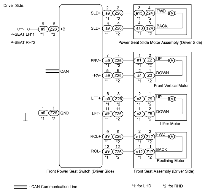
When a signal is input into the position control ECU, the ECU manages the signals received from the front power seat switch, and operates each motor. If the front power seat switch receives more than 2 motor operation signals, the motor is stopped. Manual operation is restarted after the front power seat switch receives 1 signal only.
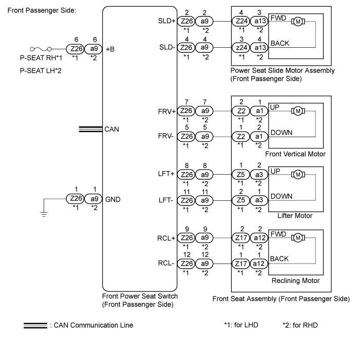
WIRING DIAGRAM
INSPECTION PROCEDURE
Tech Tips
Inspect the fuses for circuits related to this system before performing the following inspection procedure.
PROCEDURE
-
CHECK CAN COMMUNICATION SYSTEM
-
Use the intelligent tester to check if the CAN communication system is functioning normally Click here.
OK CAN communication DTC is not output.
NG 
GO TO CAN COMMUNICATION SYSTEM Click here
OK 
-
-
CHECK FRONT POWER SEAT OPERATION
-
Check that each function of the power seat operates normally by using the front power seat switch Click here.
Result Result Proceed to Some front driver side seat motors do not operate. A Some front passenger side seat motors do not operate. B
B 
READ VALUE USING INTELLIGENT TESTER Click here
A
-
-
READ VALUE USING INTELLIGENT TESTER
-
Connect the intelligent tester to the DLC3.
-
Turn the power switch on (IG).
-
Turn the intelligent tester on.
-
Enter the following menus: Body / Driver Seat / Data List.
-
Read the Data List according to the display on the intelligent tester.
Driver Seat Tester Display Measurement Item/Range Normal Condition Diagnostic Note Reclining Rear Reclining switch signal (Rearward) / ON or OFF ON: Reclining switch (Rearward) on
OFF: Reclining switch (Rearward) off
- Reclining Front Reclining switch signal (Forward) / ON or OFF ON: Reclining switch (Forward) on
OFF: Reclining switch (Forward) off
- Front Vertical Down Front vertical switch signal (Downward) / ON or OFF ON: Front vertical switch (Downward) on
OFF: Front vertical switch (Downward) off
- Front Vertical Up Front vertical switch signal (Upward) / ON or OFF ON: Front vertical switch (Upward) on
OFF: Front vertical switch (Upward) off
- Lifter Switch Down Lifter switch signal (Downward) / ON or OFF ON: Lifter switch (Downward) on
OFF: Lifter switch (Downward) off
- Lifter Switch Up Lifter switch signal (Upward) / ON or OFF ON: Lifter switch (Upward) on
OFF: Lifter switch (Upward) off
- Slide Rear Sliding switch signal (Rearward) / ON or OFF ON: Sliding switch (Rearward) on
OFF: Sliding switch (Rearward) off
- Slide Front Sliding switch signal (Forward) / ON or OFF ON: Sliding switch (Forward) on
OFF: Sliding switch (Forward) off
- OK ON or OFF is displayed on the intelligent tester according to the table above.
NG
CHECK HARNESS AND CONNECTOR (FRONT POWER SEAT SWITCH POWER SOURCE) Click here
OK
-
-
PERFORM ACTIVE TEST USING INTELLIGENT TESTER
-
Enter the following menus: Body / Driver Seat / Active Test.
-
Perform the Active Test according to the display on the intelligent tester.
Driver Seat Tester Display Test Part Control Range Diagnostic Note Seat Reclining Seat reclining operation Front / OFF / Rear - Front Vertical Operation Seat front vertical operation Up / OFF / Down - Lifter Operation Seat lifter operation Up / OFF / Down - Seat Slide Operation Seat sliding operation Front / OFF / Rear - Result Result Proceed to The power seat motors operate normally A Front vertical, lifter or reclining function does not operate normally B Slide function does not operate normally C
B
INSPECT FRONT SEAT ASSEMBLY (DRIVER SIDE) Click here
C
INSPECT POWER SEAT SLIDE MOTOR ASSEMBLY (DRIVER SIDE) Click here
A 
REPLACE FRONT POWER SEAT SWITCH (DRIVER SIDE) Click here
-
-
INSPECT POWER SEAT SLIDE MOTOR ASSEMBLY (DRIVER SIDE)
-
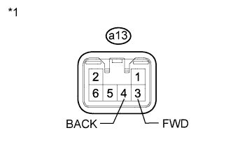
Text in Illustration *1 Component without harness connected
(Power Seat Slide Motor Assembly LH)
for LHD.
-
Remove the power seat slide motor assembly LH Click here.
-
Disconnect the a13 connector from the power seat slide motor assembly LH.
-
Check operation of the power seat slide motor assembly LH.
-
Check if the seat moves smoothly when the battery is connected to the power seat slide motor assembly LH connector terminals.
OK Measurement Condition Specified Condition Battery positive (+) → a13-3 (FWD)
Battery negative (-) → a13-4 (BACK)
Forward Battery positive (+) → a13-4 (BACK)
Battery negative (-) → a13-3 (FWD)
Rearward
-
-

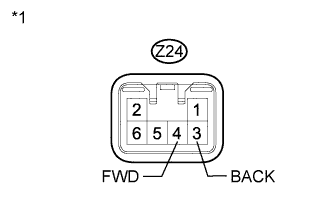
Text in Illustration *1 Component without harness connected
(Power Seat Slide Motor Assembly RH)
for RHD.
-
Remove the power seat slide motor assembly RH Click here.
-
Disconnect the Z24 connector from the power seat slide motor assembly RH.
-
Check operation of the power seat slide motor assembly RH.
-
Check if the seat moves smoothly when the battery is connected to the power seat slide motor assembly RH connector terminals.
OK Measurement Condition Specified Condition Battery positive (+) → Z24-4 (FWD)
Battery negative (-) → Z24-3 (BACK)
Forward Battery positive (+) → Z24-3 (BACK)
Battery negative (-) → Z24-4 (FWD)
Rearward
-
NG
REPLACE POWER SEAT SLIDE MOTOR ASSEMBLY (DRIVER SIDE) Click here
OK
-
-
CHECK HARNESS AND CONNECTOR (FRONT POWER SEAT SWITCH - POWER SEAT SLIDE MOTOR ASSEMBLY (DRIVER SIDE))
-
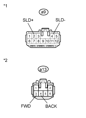
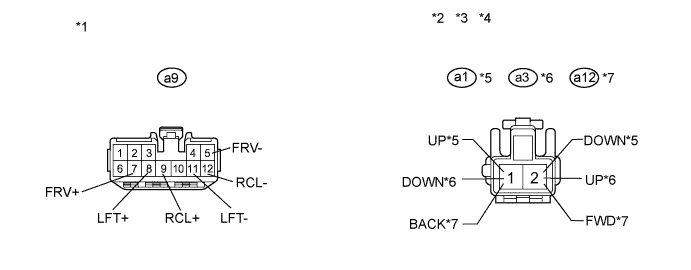
Text in Illustration *1 Front view of wire harness connector
(to Front Power Seat Switch LH)
*2 Front view of wire harness connector
(to Power Seat Slide Motor Assembly LH)
for LHD.
-
Disconnect the a9 connector from the front power seat switch LH.
-
Measure the resistance according to the value(s) in the table below.
Standard Resistance Tester Connection Condition Specified Condition a9-2 (SLD+) - a13-3 (FWD) Always Below 1 Ω a9-4 (SLD-) - a13-4 (BACK) Always Below 1 Ω a9-2 (SLD+) - Body ground Always 10 kΩ or higher a9-4 (SLD-) - Body ground Always 10 kΩ or higher
-
-

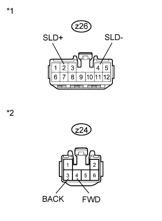
Text in Illustration *1 Front view of wire harness connector
(to Front Power Seat Switch RH)
*2 Front view of wire harness connector
(to Power Seat Slide Motor Assembly RH)
for RHD.
-
Disconnect the Z26 connector from the front power seat switch RH.
-
Measure the resistance according to the value(s) in the table below.
Standard Resistance Tester Connection Condition Specified Condition Z26-2 (SLD+) - Z24-4 (FWD) Always Below 1 Ω Z26-4 (SLD-) - Z24-3 (BACK) Always Below 1 Ω Z26-2 (SLD+) - Body ground Always 10 kΩ or higher Z26-4 (SLD-) - Body ground Always 10 kΩ or higher
-
NG
REPAIR OR REPLACE HARNESS OR CONNECTOR
OK
REPLACE FRONT POWER SEAT SWITCH (DRIVER SIDE) Click here
-
-
INSPECT FRONT SEAT ASSEMBLY (DRIVER SIDE)
-
for LHD.
-
Remove the front seat assembly LH Click here.
-
Disconnect the a1, a3 and a12 connectors from each motor.
-
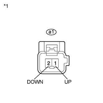
Text in Illustration *1 Component without harness connected
(Front Seat Assembly LH (Front Vertical Motor))
Check operation of the front vertical motor.
-
Check if the seat moves smoothly when the battery is connected to the front vertical motor connector terminals.
OK Measurement Condition Specified Condition Battery positive (+) → a1-1 (UP)
Battery negative (-) → a1-2 (DOWN)
Upward Battery positive (+) → a1-2 (DOWN)
Battery negative (-) → a1-1 (UP)
Downward -

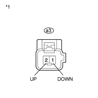
Text in Illustration *1 Component without harness connected
(Front Seat Assembly LH (Lifter Motor))
Check operation of the lifter motor.
-
Check if the seat moves smoothly when the battery is connected to the lifter motor connector terminals.
OK Measurement Condition Specified Condition Battery positive (+) → a3-2 (UP)
Battery negative (-) → a3-1 (DOWN)
Upward Battery positive (+) → a3-1 (DOWN)
Battery negative (-) → a3-2 (UP)
Downward -
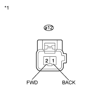
Text in Illustration *1 Component without harness connected
(Front Seat Assembly LH (Reclining Motor))
Check operation of the reclining motor.
-
Check if the seat moves smoothly when the battery is connected to the reclining motor connector terminals.
OK Measurement Condition Specified Condition Battery positive (+) → a12-2 (FWD)
Battery negative (-) → a12-1 (BACK)
Forward Battery positive (+) → a12-1 (BACK)
Battery negative (-) → a12-2 (FWD)
Rearward
-
-
for RHD.
-
Remove the front seat assembly RH Click here.
-
Disconnect the Z2, Z5 and Z17 connectors from each motor.
-
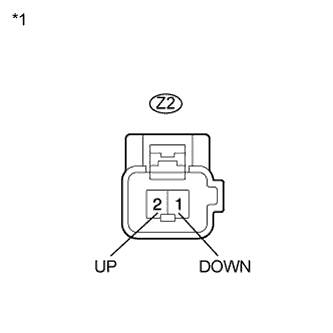
Text in Illustration *1 Component without harness connected
(Front Seat Assembly RH (Front Vertical Motor))
Check operation of the front vertical motor.
-
Check if the seat moves smoothly when the battery is connected to the front vertical motor connector terminals.
OK Measurement Condition Specified Condition Battery positive (+) → Z2-2 (UP)
Battery negative (-) → Z2-1 (DOWN)
Upward Battery positive (+) → Z2-1 (DOWN)
Battery negative (-) → Z2-2 (UP)
Downward -
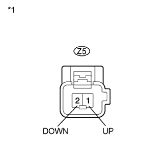
Text in Illustration *1 Component without harness connected
(Front Seat Assembly RH (Lifter Motor))
Check operation of the lifter motor.
-
Check if the seat moves smoothly when the battery is connected to the lifter motor connector terminals.
OK Measurement Condition Specified Condition Battery positive (+) → Z5-1 (UP)
Battery negative (-) → Z5-2 (DOWN)
Forward Battery positive (+) → Z5-2 (DOWN)
Battery negative (-) → Z5-1 (UP)
Rearward -

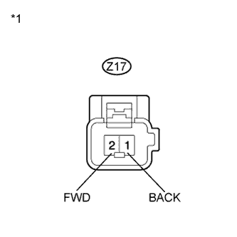
Text in Illustration *1 Component without harness connected
(Front Seat Assembly RH (Reclining Motor))
Check operation of the reclining motor.
-
Check if the seat moves smoothly when the battery is connected to the reclining motor connector terminals.
OK Measurement Condition Specified Condition Battery positive (+) → Z17-2 (FWD)
Battery negative (-) → Z17-1 (BACK)
Forward Battery positive (+) → Z17-1 (BACK)
Battery negative (-) → Z17-2 (FWD)
Rearward
-
NG
REPLACE FRONT SEAT ASSEMBLY (DRIVER SIDE) Click here
OK
-
-
CHECK HARNESS AND CONNECTOR (FRONT POWER SEAT SWITCH - FRONT SEAT ASSEMBLY)
-
for LHD.
-
Disconnect the a9 connector from the front power seat switch LH.
-
Measure the resistance according to the value(s) in the table below.
Standard Resistance Tester Connection Condition Specified Condition a9-5 (FRV-) - a1-2 (DOWN) Always Below 1 Ω a9-7 (FRV+) - a1-1 (UP) Always Below 1 Ω a9-8 (LFT+) - a3-2 (UP) Always Below 1 Ω a9-11 (LFT-) - a3-1 (DOWN) Always Below 1 Ω a9-9 (RCL+) - a12-2 (FWD) Always Below 1 Ω a9-12 (RCL-) - a12-1 (BACK) Always Below 1 Ω a9-5 (FRV-) - Body ground Always 10 kΩ or higher a9-7 (FRV+) - Body ground Always 10 kΩ or higher a9-8 (LFT+) - Body ground Always 10 kΩ or higher a9-11 (LFT-) - Body ground Always 10 kΩ or higher a9-9 (RCL+) - Body ground Always 10 kΩ or higher a9-12 (RCL-) - Body ground Always 10 kΩ or higher Text in Illustration *1 Front view of wire harness connector
(to Front Power Seat Switch LH)
*2 Front view of wire harness connector
(to Front Seat Assembly LH (Front Vertical Motor))
*3 Front view of wire harness connector
(to Front Seat Assembly LH (Lifter Motor))
*4 Front view of wire harness connector
(to Front Seat Assembly LH (Reclining Motor))
*5 Front Vertical Motor *6 Lifter Motor *7 Reclining Motor - -
-
-
for RHD.
-
Disconnect the Z26 connector from the front power seat switch RH.
-
Measure the resistance according to the value(s) in the table below.
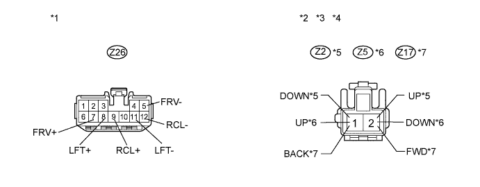
Standard Resistance Tester Connection Condition Specified Condition Z26-5 (FRV-) - Z2-1 (DOWN) Always Below 1 Ω Z26-7 (FRV+) - Z2-2 (UP) Always Below 1 Ω Z26-8 (LFT+) - Z5-1 (UP) Always Below 1 Ω Z26-11 (LFT-) - Z5-2 (DOWN) Always Below 1 Ω Z26-9 (RCL+) - Z17-2 (FWD) Always Below 1 Ω Z26-12 (RCL-) - Z17-1 (BACK) Always Below 1 Ω Z26-5 (FRV-) - Body ground Always 10 kΩ or higher Z26-7 (FRV+) - Body ground Always 10 kΩ or higher Z26-8 (LFT+) - Body ground Always 10 kΩ or higher Z26-11 (LFT-) - Body ground Always 10 kΩ or higher Z26-9 (RCL+) - Body ground Always 10 kΩ or higher Z26-12 (RCL-) - Body ground Always 10 kΩ or higher Text in Illustration *1 Front view of wire harness connector
(to Front Power Seat Switch RH)
*2 Front view of wire harness connector
(to Front Seat Assembly RH (Front Vertical Motor))
*3 Front view of wire harness connector
(to Front Seat Assembly RH (Lifter Motor))
*4 Front view of wire harness connector
(to Front Seat Assembly RH (Reclining Motor))
*5 Front Vertical Motor *6 Lifter Motor *7 Reclining Motor - -
-
NG
REPAIR OR REPLACE HARNESS OR CONNECTOR
OK
REPLACE FRONT POWER SEAT SWITCH (DRIVER SIDE) Click here
-
-
CHECK HARNESS AND CONNECTOR (FRONT POWER SEAT SWITCH POWER SOURCE)
-

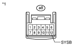
Text in Illustration *1 Front view of wire harness connector
(to Front Power Seat Switch LH)
for LHD.
-
Disconnect the a8 connector from the front power seat switch LH.
-
Measure the voltage according to the value(s) in the table below.
Standard Voltage Tester Connection Condition Specified Condition a8-12 (SYSB) - Body ground Always 11 to 14 V
-
-
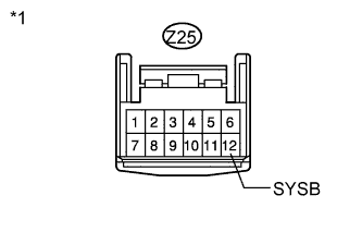
Text in Illustration *1 Front view of wire harness connector
(to Front Power Seat Switch RH)
for RHD.
-
Disconnect the Z25 connector from the front power seat switch RH.
-
Measure the voltage according to the value(s) in the table below.
Standard Voltage Tester Connection Condition Specified Condition Z25-12 (SYSB) - Body ground Always 11 to 14 V
-
NG
REPAIR OR REPLACE HARNESS OR CONNECTOR (FRONT POWER SEAT SWITCH POWER SOURCE)
OK
REPLACE FRONT POWER SEAT SWITCH (DRIVER SIDE) Click here
-
-
READ VALUE USING INTELLIGENT TESTER
-
Connect the intelligent tester to the DLC3.
-
Turn the power switch on (IG).
-
Turn the intelligent tester on.
-
Enter the following menus: Body / Passenger Seat / Data List.
-
Read the Data List according to the display on the intelligent tester.
Passenger Seat Tester Display Measurement Item/Range Normal Condition Diagnostic Note Reclining Rear Reclining switch signal (Rearward) / ON or OFF ON: Reclining switch (Rearward) on
OFF: Reclining switch (Rearward) off
- Reclining Front Reclining switch signal (Forward) / ON or OFF ON: Reclining switch (Forward) on
OFF: Reclining switch (Forward) off
- Front Vertical Down Front vertical switch signal (Downward) / ON or OFF ON: Front vertical switch (Downward) on
OFF: Front vertical switch (Downward) off
- Front Vertical Up Front vertical switch signal (Upward) / ON or OFF ON: Front vertical switch (Upward) on
OFF: Front vertical switch (Upward) off
- Lifter Switch Down Lifter switch signal (Downward) / ON or OFF ON: Lifter switch (Downward) on
OFF: Lifter switch (Downward) off
- Lifter Switch Up Lifter switch signal (Upward) / ON or OFF ON: Lifter switch (Upward) on
OFF: Lifter switch (Upward) off
- Slide Rear Sliding switch signal (Rearward) / ON or OFF ON: Sliding switch (Rearward) on
OFF: Sliding switch (Rearward) off
- Slide Front Sliding switch signal (Forward) / ON or OFF ON: Sliding switch (Forward) on
OFF: Sliding switch (Forward) off
- OK ON or OFF is displayed on the intelligent tester according to the table above.
NG
CHECK HARNESS AND CONNECTOR (FRONT POWER SEAT SWITCH POWER SOURCE) Click here
OK
-
-
PERFORM ACTIVE TEST USING INTELLIGENT TESTER
-
Enter the following menus: Body / Passenger Seat / Active Test.
-
Perform the Active Test according to the display on the intelligent tester.
Driver Seat Tester Display Test Part Control Range Diagnostic Note Seat Reclining Seat reclining operation Front / OFF / Rear - Front Vertical Operation Seat front vertical operation Up / OFF / Down - Lifter Operation Seat lifter operation Up / OFF / Down - Seat Slide Operation Seat sliding operation Front / OFF / Rear - Result Result Proceed to The power seat motors operate normally A Front vertical, lifter or reclining function does not operate normally B Slide function does not operate normally C
B
INSPECT FRONT SEAT ASSEMBLY (FRONT PASSENGER SIDE) Click here
C
INSPECT POWER SEAT SLIDE MOTOR ASSEMBLY (FRONT PASSENGER SIDE) Click here
A
REPLACE FRONT POWER SEAT SWITCH (DRIVER SIDE) Click here
-
-
INSPECT POWER SEAT SLIDE MOTOR ASSEMBLY (FRONT PASSENGER SIDE)
-
Text in Illustration *1 Component without harness connected
(Power Seat Slide Motor Assembly RH)
for LHD.
-
Remove the power seat side motor assembly RH Click here.
-
Disconnect the Z24 connector from the power seat slide motor assembly RH.
-
Check operation of the power seat slide motor assembly RH.
-
Check if the seat moves smoothly when the battery is connected to the power seat slide motor assembly RH connector terminals.
OK Measurement Condition Specified Condition Battery positive (+) → Z24-4 (FWD)
Battery negative (-) → Z24-3 (BACK)
Forward Battery positive (+) → Z24-3 (BACK)
Battery negative (-) → Z24-4 (FWD)
Rearward
-
-

Text in Illustration *1 Component without harness connected
(Power Seat Slide Motor Assembly LH)
for RHD.
-
Remove the power seat side motor assembly LH Click here.
-
Disconnect the a13 connector from the power seat slide motor assembly LH.
-
Check operation of the power seat slide motor assembly LH.
-
Check if the seat moves smoothly when the battery is connected to the power seat slide motor assembly LH connector terminals.
OK Measurement Condition Specified Condition Battery positive (+) → a13-3 (FWD)
Battery negative (-) → a13-4 (BACK)
Forward Battery positive (+) → a13-4 (BACK)
Battery negative (-) → a13-3 (FWD)
Rearward
-
NG
REPLACE POWER SEAT SLIDE MOTOR ASSEMBLY (FRONT PASSENGER SIDE) Click here
OK
-
-
CHECK HARNESS AND CONNECTOR (FRONT POWER SEAT SWITCH - POWER SEAT SLIDE MOTOR ASSEMBLY (FRONT PASSENGER SIDE))
-
Text in Illustration *1 Front view of wire harness connector
(to Front Power Seat Switch RH)
*2 Front view of wire harness connector
(to Power Seat Slide Motor Assembly RH)
for LHD.
-
Disconnect the Z26 connector from the front power seat switch RH.
-
Measure the resistance according to the value(s) in the table below.
Standard Resistance Tester Connection Condition Specified Condition Z26-2 (SLD+) - Z24-4 (FWD) Always Below 1 Ω Z26-4 (SLD-) - Z24-3 (BACK) Always Below 1 Ω Z26-2 (SLD+) - Body ground Always 10 kΩ or higher Z26-4 (SLD-) - Body ground Always 10 kΩ or higher
-
-

Text in Illustration *1 Front view of wire harness connector
(to Front Power Seat Switch LH)
*2 Front view of wire harness connector
(to Power Seat Slide Motor Assembly LH)
for RHD.
-
Disconnect the a9 connector from the front power seat switch LH.
-
Measure the resistance according to the value(s) in the table below.
Standard Resistance Tester Connection Condition Specified Condition a9-2 (SLD+) - a13-3 (FWD) Always Below 1 Ω a9-4 (SLD-) - a13-4 (BACK) Always Below 1 Ω a9-2 (SLD+) - Body ground Always 10 kΩ or higher a9-4 (SLD-) - Body ground Always 10 kΩ or higher
-
NG
REPAIR OR REPLACE HARNESS OR CONNECTOR
OK
REPLACE FRONT POWER SEAT SWITCH (FRONT PASSENGER SIDE) Click here
-
-
INSPECT FRONT SEAT ASSEMBLY (FRONT PASSENGER SIDE)
-
for LHD.
-
Remove the front seat assembly RH Click here.
-
Disconnect the Z2, Z5 and Z17 connectors from each motor.
-

Text in Illustration *1 Component without harness connected
(Front Seat Assembly RH (Front Vertical Motor))
Check operation of the front vertical motor.
-
Check if the seat moves smoothly when the battery is connected to the front vertical motor connector terminals.
OK Measurement Condition Specified Condition Battery positive (+) → Z2-2 (UP)
Battery negative (-) → Z2-1 (DOWN)
Upward Battery positive (+) → Z2-1 (DOWN)
Battery negative (-) → Z2-2 (UP)
Downward -

Text in Illustration *1 Component without harness connected
(Front Seat Assembly RH (Lifter Motor))
Check operation of the lifter motor.
-
Check if the seat moves smoothly when the battery is connected to the lifter motor connector terminals.
OK Measurement Condition Specified Condition Battery positive (+) → Z5-1 (UP)
Battery negative (-) → Z5-2 (DOWN)
Forward Battery positive (+) → Z5-2 (DOWN)
Battery negative (-) → Z5-1 (UP)
Rearward -
Text in Illustration *1 Component without harness connected
(Front Seat Assembly RH (Reclining Motor))
Check operation of the reclining motor.
-
Check if the seat moves smoothly when the battery is connected to the reclining motor connector terminals.
OK Measurement Condition Specified Condition Battery positive (+) → Z17-2 (FWD)
Battery negative (-) → Z17-1 (BACK)
Forward Battery positive (+) → Z17-1 (BACK)
Battery negative (-) → Z17-2 (FWD)
Rearward
-
-
for RHD.
-
Remove the front seat assembly LH Click here.
-
Disconnect the a1, a3 and a12 connectors from each motor.
-

Text in Illustration *1 Component without harness connected
(Front Seat Assembly LH (Front Vertical Motor))
Check operation of the front vertical motor.
-
Check if the seat moves smoothly when the battery is connected to the front vertical motor connector terminals.
OK Measurement Condition Specified Condition Battery positive (+) → a1-1 (UP)
Battery negative (-) → a1-2 (DOWN)
Upward Battery positive (+) → a1-2 (DOWN)
Battery negative (-) → a1-1 (UP)
Downward -
Text in Illustration *1 Component without harness connected
(Front Seat Assembly LH (Lifter Motor))
Check operation of the lifter motor.
-
Check if the seat moves smoothly when the battery is connected to the lifter motor connector terminals.
OK Measurement Condition Specified Condition Battery positive (+) → a3-2 (UP)
Battery negative (-) → a3-1 (DOWN)
Forward Battery positive (+) → a3-1 (DOWN)
Battery negative (-) → a3-2 (UP)
Rearward -

Text in Illustration *1 Component without harness connected
(Front Seat Assembly LH (Reclining Motor))
Check operation of the reclining motor.
-
Check if the seat moves smoothly when the battery is connected to the reclining motor connector terminals.
OK Measurement Condition Specified Condition Battery positive (+) → a12-2 (FWD)
Battery negative (-) → a12-1 (BACK)
Forward Battery positive (+) → a12-1 (BACK)
Battery negative (-) → a12-2 (FWD)
Rearward
-
NG
REPLACE FRONT SEAT ASSEMBLY (FRONT PASSENGER SIDE) Click here
OK
-
-
CHECK HARNESS AND CONNECTOR (FRONT POWER SEAT SWITCH - FRONT SEAT ASSEMBLY)
-
for LHD.

-
Disconnect the Z26 connector from the front power seat switch RH.
-
Measure the resistance according to the value(s) in the table below.
Standard Resistance Tester Connection Condition Specified Condition Z26-5 (FRV-) - Z2-1 (DOWN) Always Below 1 Ω Z26-7 (FRV+) - Z2-2 (UP) Always Below 1 Ω Z26-8 (LFT+) - Z5-1 (UP) Always Below 1 Ω Z26-11 (LFT-) - Z5-2 (DOWN) Always Below 1 Ω Z26-9 (RCL+) - Z17-2 (FWD) Always Below 1 Ω Z26-12 (RCL-) - Z17-1 (BACK) Always Below 1 Ω Z26-5 (FRV-) - Body ground Always 10 kΩ or higher Z26-7 (FRV+) - Body ground Always 10 kΩ or higher Z26-8 (LFT+) - Body ground Always 10 kΩ or higher Z26-11 (LFT-) - Body ground Always 10 kΩ or higher Z26-9 (RCL+) - Body ground Always 10 kΩ or higher Z26-12 (RCL-) - Body ground Always 10 kΩ or higher Text in Illustration *1 Front view of wire harness connector
(to Front Power Seat Switch RH)
*2 Front view of wire harness connector
(to Front Seat Assembly RH (Front Vertical Motor))
*3 Front view of wire harness connector
(to Front Seat Assembly RH (Lifter Motor))
*4 Front view of wire harness connector
(to Front Seat Assembly RH (Reclining Motor))
*5 Front Vertical Motor *6 Lifter Motor *7 Reclining Motor - -
-
-
for RHD.

-
Disconnect the a9 connector from the front power seat switch LH.
-
Measure the resistance according to the value(s) in the table below.
Standard Resistance Tester Connection Condition Specified Condition a9-5 (FRV-) - a1-2 (DOWN) Always Below 1 Ω a9-7 (FRV+) - a1-1 (UP) Always Below 1 Ω a9-8 (LFT+) - a3-2 (UP) Always Below 1 Ω a9-11 (LFT-) - a3-1 (DOWN) Always Below 1 Ω a9-9 (RCL+) - a12-2 (FWD) Always Below 1 Ω a9-12 (RCL-) - a12-1 (BACK) Always Below 1 Ω a9-5 (FRV-) - Body ground Always 10 kΩ or higher a9-7 (FRV+) - Body ground Always 10 kΩ or higher a9-8 (LFT+) - Body ground Always 10 kΩ or higher a9-11 (LFT-) - Body ground Always 10 kΩ or higher a9-9 (RCL+) - Body ground Always 10 kΩ or higher a9-12 (RCL-) - Body ground Always 10 kΩ or higher Text in Illustration *1 Front view of wire harness connector
(to Front Power Seat Switch LH)
*2 Front view of wire harness connector
(to Front Seat Assembly LH (Front Vertical Motor))
*3 Front view of wire harness connector
(to Front Seat Assembly LH (Lifter Motor))
*4 Front view of wire harness connector
(to Front Seat Assembly LH (Reclining Motor))
*5 Front Vertical Motor *6 Lifter Motor *7 Reclining Motor - -
-
NG
REPAIR OR REPLACE HARNESS OR CONNECTOR
OK
REPLACE FRONT POWER SEAT SWITCH (FRONT PASSENGER SIDE) Click here
-
-
CHECK HARNESS AND CONNECTOR (FRONT POWER SEAT SWITCH POWER SOURCE)
-

Text in Illustration *1 Front view of wire harness connector
(to Front Power Seat Switch RH)
for LHD.
-
Disconnect the Z25 connector from the front power seat switch RH.
-
Measure the voltage according to the value(s) in the table below.
Standard Voltage Tester Connection Condition Specified Condition Z25-12 (SYSB) - Body ground Always 11 to 14 V
-
-
Text in Illustration *1 Front view of wire harness connector
(to Front Power Seat Switch LH)
for RHD.
-
Disconnect the a8 connector from the front power seat switch LH.
-
Measure the voltage according to the value(s) in the table below.
Standard Voltage Tester Connection Condition Specified Condition a8-12 (SYSB) - Body ground Always 11 to 14 V
-
NG
REPAIR OR REPLACE HARNESS OR CONNECTOR
OK
REPLACE FRONT POWER SEAT SWITCH (FRONT PASSENGER SIDE) Click here
-