FRONT POWER SEAT CONTROL SYSTEM (w/ Memory) Front Power Seat does not Operate with Front Power Seat Switch
DESCRIPTION
When a signal is input into the position control ECU, the ECU manages the signals received from the front power seat switch, and operates each motor. If the front power seat switch receives more than 2 motor operation signals, the motor is stopped. Manual operation is restarted after the front power seat switch receives 1 signal only.
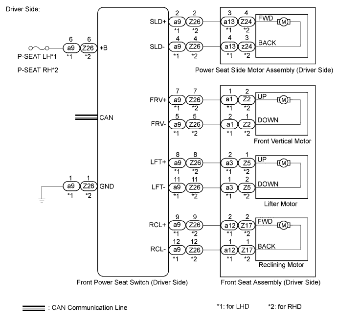
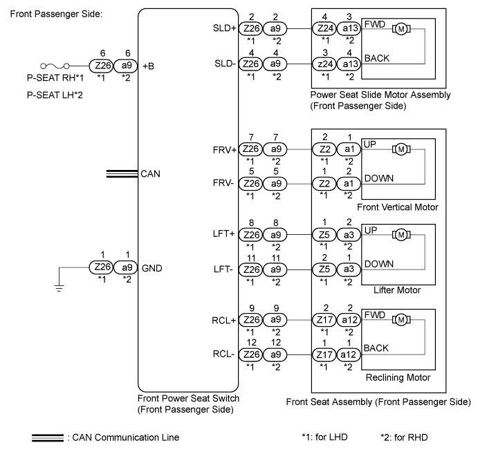
WIRING DIAGRAM
INSPECTION PROCEDURE
Tech Tips
Inspect the fuses for circuits related to this system before performing the following inspection procedure.
PROCEDURE
-
CHECK CAN COMMUNICATION SYSTEM
-
Use the intelligent tester to check if the CAN communication system is functioning normally Click here.
OK CAN communication DTC is not output.
NG 
GO TO CAN COMMUNICATION SYSTEM Click here
OK 
-
-
CHECK FRONT POWER SEAT OPERATION
-
Check that each function of the power seat operates normally by using the front power seat switch Click here.
Result Result Proceed to Driver side power seat control function does not operate A Front passenger side power seat control function does not operate B
B 
CHECK FRONT POWER SEAT OPERATION Click here
A
-
-
CHECK FRONT POWER SEAT OPERATION
-
Check that each function of the power seat operates normally by using the front power seat switch Click here.
Result Result Proceed to All power seat functions do not operate A One or more power seat motors do not operate B
B
GO TO OTHER FLOW CHART (One or more Power Seat Motors do not Operate) Click here
A
-
-
CHECK HARNESS AND CONNECTOR (FRONT POWER SEAT SWITCH POWER SOURCE)
-
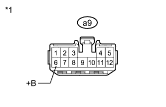
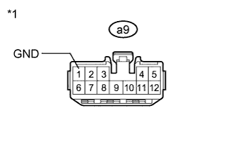
Text in Illustration *1 Front view of wire harness connector
(to Front Power Seat Switch LH)
for LHD.
-
Disconnect the a9 connector from the front power seat switch LH.
-
Measure the voltage according to the value(s) in the table below.
Standard Voltage Tester Connection Condition Specified Condition a9-6 (+B) - Body ground Always 11 to 14 V
-
-
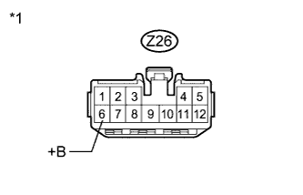
Text in Illustration *1 Front view of wire harness connector
(to Front Power Seat Switch RH)
for RHD.
-
Disconnect the Z26 connector from the front power seat switch RH.
-
Measure the voltage according to the value(s) in the table below.
Standard Voltage Tester Connection Condition Specified Condition Z26-6 (+B) - Body ground Always 11 to 14 V
-
NG
REPAIR OR REPLACE HARNESS OR CONNECTOR (FRONT POWER SEAT SWITCH POWER SOURCE)
OK
-
-
CHECK HARNESS AND CONNECTOR (BODY GROUND)
-

Text in Illustration *1 Front view of wire harness connector
(to Front Power Seat Switch LH)
for LHD.
-
Measure the resistance according to the value(s) in the table below.
Standard Resistance Tester Connection Condition Specified Condition a9-1 (GND) - Body ground Always Below 1 Ω
-
-
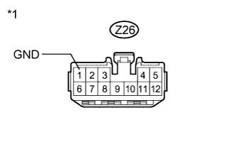
Text in Illustration *1 Front view of wire harness connector
(to Front Power Seat Switch RH)
for RHD.
-
Measure the resistance according to the value(s) in the table below.
Standard Resistance Tester Connection Condition Specified Condition Z26-1 (GND) - Body ground Always Below 1 Ω
-
NG
REPAIR OR REPLACE HARNESS OR CONNECTOR
OK 
REPLACE FRONT POWER SEAT SWITCH (DRIVER SIDE) Click here
-
-
CHECK FRONT POWER SEAT OPERATION
-
Check that each function of the power seat operates normally by using the front power seat switch Click here.
Result Result Proceed to All power seat functions do not operate A One or more power seat motors do not operate B
B
GO TO OTHER FLOW CHART (One or more Power Seat Motors do not Operate) Click here
A
-
-
CHECK HARNESS AND CONNECTOR (FRONT POWER SEAT SWITCH POWER SOURCE)
-

Text in Illustration *1 Front view of wire harness connector
(to Front Power Seat Switch RH)
for LHD.
-
Disconnect the Z26 connector from the front power seat switch RH.
-
Measure the voltage according to the value(s) in the table below.
Standard Voltage Tester Connection Condition Specified Condition Z26-6 (+B) - Body ground Always 11 to 14 V
-
-

Text in Illustration *1 Front view of wire harness connector
(to Front Power Seat Switch LH)
for RHD.
-
Disconnect the a9 connector from the front power seat switch LH.
-
Measure the voltage according to the value(s) in the table below.
Standard Voltage Tester Connection Condition Specified Condition a9-6 (+B) - Body ground Always 11 to 14 V
-
NG
REPAIR OR REPLACE HARNESS OR CONNECTOR
OK
-
-
CHECK HARNESS AND CONNECTOR (BODY GROUND)
-

Text in Illustration *1 Front view of wire harness connector
(to Front Power Seat Switch RH)
for LHD.
-
Measure the resistance according to the value(s) in the table below.
Standard Resistance Tester Connection Condition Specified Condition Z26-1 (GND) - Body ground Always Below 1 Ω
-
-
Text in Illustration *1 Front view of wire harness connector
(to Front Power Seat Switch LH)
for RHD.
-
Measure the resistance according to the value(s) in the table below.
Standard Resistance Tester Connection Condition Specified Condition a9-1 (GND) - Body ground Always Below 1 Ω
-
NG
REPAIR OR REPLACE HARNESS OR CONNECTOR
OK
REPLACE FRONT POWER SEAT SWITCH (FRONT PASSENGER SIDE) Click here
-