FRONT POWER SEAT CONTROL SYSTEM (w/ Memory), Diagnostic DTC:B2658

| DTC Code | DTC Name |
|---|---|
| B2658 | Short in Sensor with Motor Power Supply Circuit |
DESCRIPTION
This DTC is stored if sensor voltage does not reach the designated voltage while the power seat slide motor assembly is operating.
| DTC Code | DTC Detection Condition | Trouble Area |
|---|---|---|
| B2658 | Malfunction in supply voltage for the seat slide control position sensor |
|
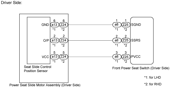
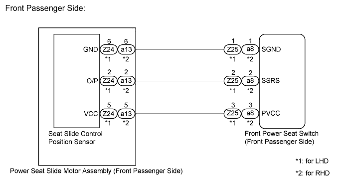
WIRING DIAGRAM
INSPECTION PROCEDURE
Tech Tips
Inspect the fuses for circuits related to this system before performing the following inspection procedure.
PROCEDURE
-
CHECK FOR DTC
-
Connect the intelligent tester to the DLC3.
-
Turn the power switch on (IG).
-
Turn the intelligent tester on.
-
Enter the following menus: Body / Driver Seat / Trouble Codes.
-
Clear the DTC Click here.
-
Recheck for DTC B2658.
Result Result Proceed to B2658 output from driver seat ECU A B2658 output from front passenger seat ECU B
B 
CHECK HARNESS AND CONNECTOR (FRONT POWER SEAT SWITCH - POWER SEAT SLIDE MOTOR ASSEMBLY (FRONT PASSENGER SIDE)) Click here
A 
-
-
CHECK HARNESS AND CONNECTOR (FRONT POWER SEAT SWITCH - POWER SEAT SLIDE MOTOR ASSEMBLY (DRIVER SIDE))
-

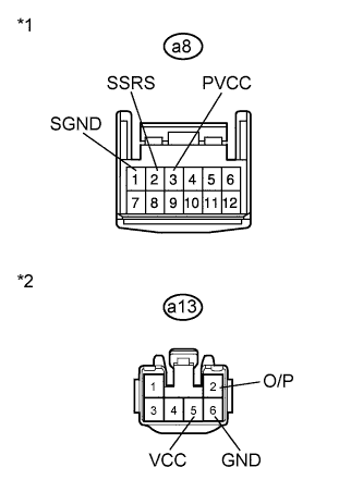
Text in Illustration *1 Front view of wire harness connector
(to Front Power Seat Switch LH)
*2 Front view of wire harness connector
(to Power Seat Slide Motor Assembly LH)
for LHD.
-
Disconnect the a8 connector from the front power seat switch LH.
-
Disconnect the a13 connector from the power seat slide motor assembly LH.
-
Measure the resistance according to the value(s) in the table below.
Standard Resistance Tester Connection Condition Specified Condition a8-3 (PVCC) - a13-5 (VCC) Always Below 1 Ω a8-2 (SSRS) - a13-2 (O/P) Always Below 1 Ω a8-1 (SGND) - a13-6 (GND) Always Below 1 Ω a8-3 (PVCC) - Body ground Always 10 kΩ or higher a8-2 (SSRS) - Body ground Always 10 kΩ or higher a8-1 (SGND) - Body ground Always 10 kΩ or higher
-
-
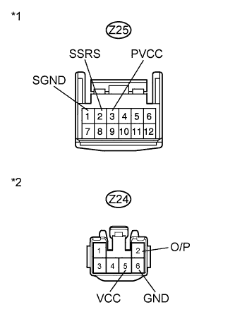
Text in Illustration *1 Front view of wire harness connector
(to Front Power Seat Switch RH)
*2 Front view of wire harness connector
(to Power Seat Slide Motor Assembly RH)
for RHD.
-
Disconnect the Z25 connector from the front power seat switch RH.
-
Disconnect the Z24 connector from the power seat slide motor assembly RH.
-
Measure the resistance according to the value(s) in the table below.
Standard Resistance Tester Connection Condition Specified Condition Z25-3 (PVCC) - Z24-5 (VCC) Always Below 1 Ω Z25-2 (SSRS) - Z24-2 (O/P) Always Below 1 Ω Z25-1 (SGND) - Z24-6 (GND) Always Below 1 Ω Z25-3 (PVCC) - Body ground Always 10 kΩ or higher Z25-2 (SSRS) - Body ground Always 10 kΩ or higher Z25-1 (SGND) - Body ground Always 10 kΩ or higher
-
NG 
REPAIR OR REPLACE HARNESS OR CONNECTOR
OK
-
-
CHECK POWER SEAT SLIDE MOTOR ASSEMBLY (DRIVER SIDE) (SEAT SLIDE POSITION SENSOR)
-

Text in Illustration *1 Front view of wire harness connector
(to Power Seat Slide Motor Assembly LH)
for LHD.
-
Reconnect the a8 connector to the front power seat switch LH.
-
Measure the voltage according to the value(s) in the table below.
Standard Voltage Tester Connection Condition Specified Condition a13-5 (VCC) - a13-6 (GND) Slide switch on 5.5 to 6.5 V
-
-
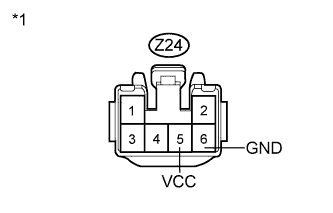
Text in Illustration *1 Front view of wire harness connector
(to Power Seat Slide Motor Assembly RH)
for RHD.
-
Reconnect the Z25 connector to the front power seat switch RH.
-
Measure the voltage according to the value(s) in the table below.
Standard Voltage Tester Connection Condition Specified Condition Z24-5 (VCC) - Z24-6 (GND) Slide switch on 5.5 to 6.5 V
-
NG
REPLACE FRONT POWER SEAT SWITCH (DRIVER SIDE) Click here
OK 
REPLACE POWER SEAT SLIDE MOTOR ASSEMBLY (DRIVER SIDE) Click here
-
-
CHECK HARNESS AND CONNECTOR (FRONT POWER SEAT SWITCH - POWER SEAT SLIDE MOTOR ASSEMBLY (FRONT PASSENGER SIDE))
-

Text in Illustration *1 Front view of wire harness connector
(to Front Power Seat Switch RH)
*2 Front view of wire harness connector
(to Power Seat Slide Motor Assembly RH)
for LHD.
-
Disconnect the Z25 connector from the front power seat switch RH.
-
Disconnect the Z24 connector from the power seat slide motor assembly RH.
-
Measure the resistance according to the value(s) in the table below.
Standard Resistance Tester Connection Condition Specified Condition Z25-3 (PVCC) - Z24-5 (VCC) Always Below 1 Ω Z25-2 (SSRS) - Z24-2 (O/P) Always Below 1 Ω Z25-1 (SGND) - Z24-6 (GND) Always Below 1 Ω Z25-3 (PVCC) - Body ground Always 10 kΩ or higher Z25-2 (SSRS) - Body ground Always 10 kΩ or higher Z25-1 (SGND) - Body ground Always 10 kΩ or higher
-
-
Text in Illustration *1 Front view of wire harness connector
(to Front Power Seat Switch LH)
*2 Front view of wire harness connector
(to Power Seat Slide Motor Assembly LH)
for RHD.
-
Disconnect the a8 connector from the front power seat switch LH.
-
Disconnect the a13 connector from the power seat slide motor assembly LH.
-
Measure the resistance according to the value(s) in the table below.
Standard Resistance Tester Connection Condition Specified Condition a8-3 (PVCC) - a13-5 (VCC) Always Below 1 Ω a8-2 (SSRS) - a13-2 (O/P) Always Below 1 Ω a8-1 (SGND) - a13-6 (GND) Always Below 1 Ω a8-3 (PVCC) - Body ground Always 10 kΩ or higher a8-2 (SSRS) - Body ground Always 10 kΩ or higher a8-1 (SGND) - Body ground Always 10 kΩ or higher
-
NG
REPAIR OR REPLACE HARNESS OR CONNECTOR
OK
-
-
CHECK POWER SEAT SLIDE MOTOR ASSEMBLY (FRONT PASSENGER SIDE) (SEAT SLIDE POSITION SENSOR)
-

Text in Illustration *1 Front view of wire harness connector
(to Power Seat Slide Motor Assembly RH)
for LHD.
-
Reconnect the Z25 connector to the front power seat switch RH.
-
Measure the voltage according to the value(s) in the table below.
Standard Voltage Tester Connection Condition Specified Condition Z24-5 (VCC) - Z24-6 (GND) Slide switch on 5.5 to 6.5 V
-
-

Text in Illustration *1 Front view of wire harness connector
(to Power Seat Slide Motor Assembly LH)
for RHD.
-
Reconnect the a8 connector to the front power seat switch LH.
-
Measure the voltage according to the value(s) in the table below.
Standard Voltage Tester Connection Condition Specified Condition a13-5 (VCC) - a13-6 (GND) Slide switch on 5.5 to 6.5 V
-
NG
REPLACE FRONT POWER SEAT SWITCH (FRONT PASSENGER SIDE) Click here
OK
REPLACE POWER SEAT SLIDE MOTOR ASSEMBLY (FRONT PASSENGER SIDE) Click here
-