FRONT POWER SEAT CONTROL SYSTEM (w/ Memory), Diagnostic DTC:B2650

| DTC Code | DTC Name |
|---|---|
| B2650 | Slide Sensor Malfunction |
DESCRIPTION
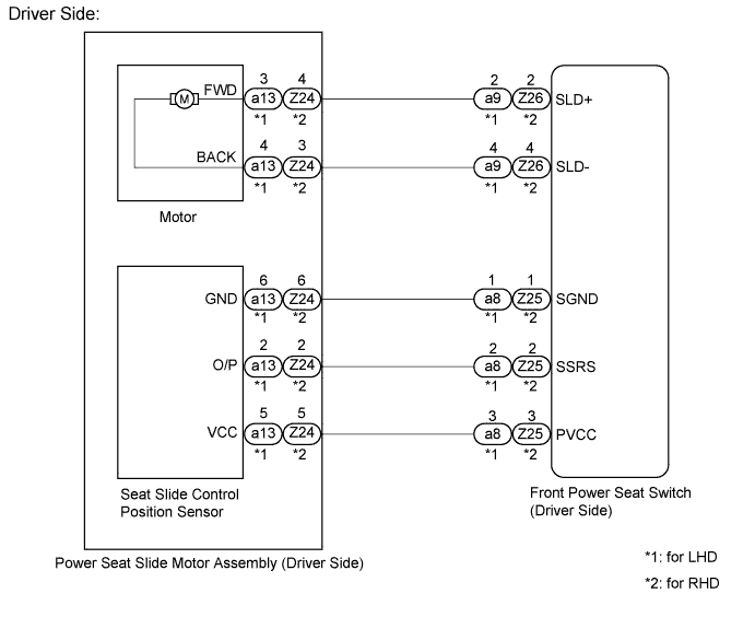
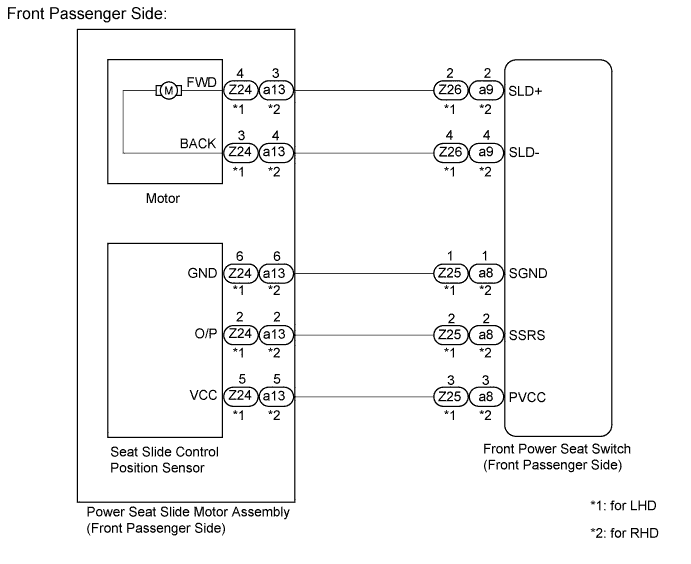
When the front power seat switch (seat ECU) does not receive a sensor signal despite forward or backward movement of seat by power seat motor operation, this DTC is output.
| DTC Code | DTC Detection Condition | Trouble Area |
|---|---|---|
| B2650 | Sensor's forward and backward lock detection position is the same |
|
WIRING DIAGRAM
INSPECTION PROCEDURE
Tech Tips
Inspect the fuses for circuits related to this system before performing the following inspection procedure.
PROCEDURE
-
CHECK FOR DTC
-
Connect the intelligent tester to the DLC3.
-
Turn the power switch on (IG).
-
Turn the intelligent tester on.
-
Enter the following menus: Body / Driver Seat / Trouble Codes.
-
Clear the DTC Click here.
-
Recheck for DTC B2650.
Result Result Proceed to B2650 output from driver seat ECU A B2650 output from front passenger seat ECU B
B 
PERFORM ACTIVE TEST USING INTELLIGENT TESTER Click here
A 
-
-
PERFORM ACTIVE TEST USING INTELLIGENT TESTER
-
Enter the following menus: Body / Driver Seat / Active Test.
-
Perform the Active Test according to the display on the intelligent tester.
Driver Seat Tester Display Test Part Control Range Diagnostic Note Seat Slide Operation Seat sliding operation Front / OFF / Rear - OK Motor operates normally.
NG
INSPECT POWER SEAT SLIDE MOTOR ASSEMBLY (DRIVER SIDE) Click here
OK
-
-
CHECK HARNESS AND CONNECTOR (FRONT POWER SEAT SWITCH - POWER SEAT SLIDE MOTOR ASSEMBLY (DRIVER SIDE))
-
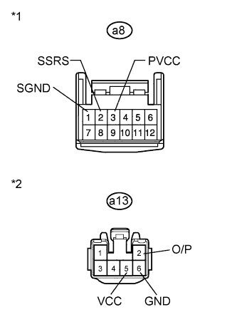
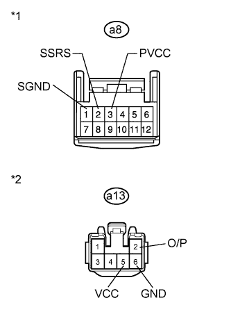
Text in Illustration *1 Front view of wire harness connector
(to Front Power Seat Switch LH)
*2 Front view of wire harness connector
(to Power Seat Slide Motor Assembly LH)
for LHD.
-
Disconnect the a8 connector from the front power seat switch LH.
-
Disconnect the a13 connector from the power seat slide motor assembly LH.
-
Measure the resistance according to the value(s) in the table below.
Standard Resistance Tester Connection Condition Specified Condition a8-3 (PVCC) - a13-5 (VCC) Always Below 1 Ω a8-2 (SSRS) - a13-2 (O/P) Always Below 1 Ω a8-1 (SGND) - a13-6 (GND) Always Below 1 Ω a8-3 (PVCC) - Body ground Always 10 kΩ or higher a8-2 (SSRS) - Body ground Always 10 kΩ or higher a8-1 (SGND) - Body ground Always 10 kΩ or higher
-
-
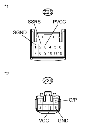
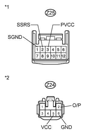
Text in Illustration *1 Front view of wire harness connector
(to Front Power Seat switch RH)
*2 Front view of wire harness connector
(to Power Seat Slide Motor Assembly RH)
for RHD.
-
Disconnect the Z25 connector from the front power seat switch RH.
-
Disconnect the Z24 connector from the power seat slide motor assembly RH.
-
Measure the resistance according to the value(s) in the table below.
Standard Resistance Tester Connection Condition Specified Condition Z25-3 (PVCC) - Z24-5 (VCC) Always Below 1 Ω Z25-2 (SSRS) - Z24-2 (O/P) Always Below 1 Ω Z25-1 (SGND) - Z24-6 (GND) Always Below 1 Ω Z25-3 (PVCC) - Body ground Always 10 kΩ or higher Z25-2 (SSRS) - Body ground Always 10 kΩ or higher Z25-1 (SGND) - Body ground Always 10 kΩ or higher
-
NG 
REPAIR OR REPLACE HARNESS OR CONNECTOR (FRONT POWER SEAT SWITCH - POWER SEAT SLIDE MOTOR ASSEMBLY (DRIVER SIDE))
OK
-
-
CHECK POWER SEAT SLIDE MOTOR ASSEMBLY (DRIVER SIDE)
-

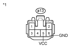
Text in Illustration *1 Front view of wire harness connector
(to Power Seat Slide Motor Assembly LH)
for LHD.
-
Reconnect the a8 connector to the front power seat switch LH.
-
Measure the voltage according to the value(s) in the table below.
Standard Voltage Tester Connection Condition Specified Condition a13-5 (VCC) - a13-6 (GND) Slide switch on 5.5 to 6.5 V
-
-

Text in Illustration *1 Front view of wire harness connector
(to Power Seat Slide Motor Assembly RH)
for RHD.
-
Reconnect the Z25 connector to the front power seat switch RH.
-
Measure the voltage according to the value(s) in the table below.
Standard Voltage Tester Connection Condition Specified Condition Z24-5 (VCC) - Z24-6 (GND) Slide switch on 5.5 to 6.5 V
-
NG
REPLACE FRONT POWER SEAT SWITCH (DRIVER SIDE) Click here
OK 
REPLACE POWER SEAT SLIDE MOTOR ASSEMBLY (DRIVER SIDE) Click here
-
-
INSPECT POWER SEAT SLIDE MOTOR ASSEMBLY (DRIVER SIDE)
-
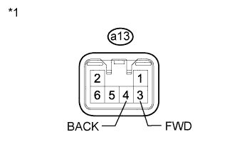
Text in Illustration *1 Component without harness connected
(Power Seat Slide Motor Assembly LH)
for LHD.
-
Disconnect the a13 connector from the power seat slide motor assembly LH.
-
Check if the seat frame moves smoothly when the battery is connected to the power seat slide motor assembly LH connector terminals.
OK Measurement Condition Operational Direction Battery Positive (+) → a13-3 (FWD)
Battery Negative (-) → a13-4 (BACK)
Forward Battery Positive (+) → a13-4 (BACK)
Battery Negative (-) → a13-3 (FWD)
Backward
-
-
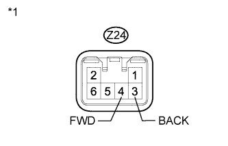
Text in Illustration *1 Component without harness connected
(Power Seat Slide Motor Assembly RH)
for RHD.
-
Disconnect the Z24 connector from the power seat slide motor assembly RH.
-
Check if the seat frame moves smoothly when the battery is connected to the power seat slide motor assembly RH connector terminals.
OK Measurement Condition Operational Direction Battery Positive (+) → Z24-4 (FWD)
Battery Negative (-) → Z24-3 (BACK)
Forward Battery Positive (+) → Z24-3 (BACK)
Battery Negative (-) → Z24-4 (FWD)
Backward
-
NG
REPLACE POWER SEAT SLIDE MOTOR ASSEMBLY (DRIVER SIDE) Click here
OK
-
-
CHECK HARNESS AND CONNECTOR (FRONT POWER SEAT SWITCH - POWER SEAT SLIDE MOTOR ASSEMBLY (DRIVER SIDE))
-
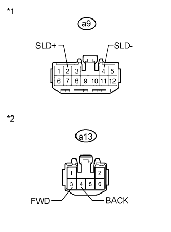
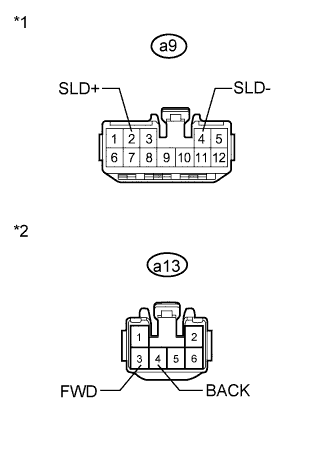
Text in Illustration *1 Front view of wire harness connector
(to Front Power Seat Switch LH)
*2 Front view of wire harness connector
(to Power Seat Slide Motor Assembly LH)
for LHD.
-
Disconnect the a9 connector from the front power seat switch LH.
-
Measure the resistance according to the value(s) in the table below.
Standard Resistance Tester Connection Condition Specified Condition a9-2 (SLD+) - a13-3 (FWD) Always Below 1 Ω a9-4 (SLD-) - a13-4 (BACK) Always Below 1 Ω a9-2 (SLD+) - a13-3 (FWD) Always 10 kΩ or higher a9-4 (SLD-) - a13-4 (BACK) Always 10 kΩ or higher
-
-
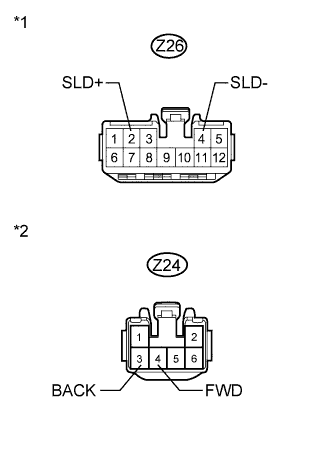
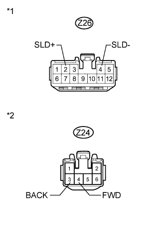
Text in Illustration *1 Front view of wire harness connector
(to Front Power Seat Switch RH)
*2 Front view of wire harness connector
(to Power Seat Slide Motor Assembly RH)
for RHD.
-
Disconnect the Z26 connector from the front power seat switch RH.
-
Measure the resistance according to the value(s) in the table below.
Standard Resistance Tester Connection Condition Specified Condition Z26-2 (SLD+) - Z24-4 (FWD) Always Below 1 Ω Z26-4 (SLD-) - Z24-3 (BACK) Always Below 1 Ω Z26-2 (SLD+) - Z24-4 (FWD) Always 10 kΩ or higher Z26-4 (SLD-) - Z24-3 (BACK) Always 10 kΩ or higher
-
NG
REPAIR OR REPLACE HARNESS OR CONNECTOR (FRONT POWER SEAT SWITCH - POWER SEAT SLIDE MOTOR ASSEMBLY (DRIVER SIDE))
OK
REPLACE FRONT POWER SEAT SWITCH (DRIVER SIDE) Click here
-
-
PERFORM ACTIVE TEST USING INTELLIGENT TESTER
-
Enter the following menus: Body / Passenger Seat / Active Test.
-
Perform the Active Test according to the display on the intelligent tester.
Passenger Seat Tester Display Test Part Control Range Diagnostic Note Seat Slide Operation Seat sliding operation Front / OFF / Rear - OK Motor operates normally.
NG
INSPECT POWER SEAT SLIDE MOTOR ASSEMBLY (FRONT PASSENGER SIDE) Click here
OK
-
-
CHECK HARNESS AND CONNECTOR (FRONT POWER SEAT SWITCH - POWER SEAT SLIDE MOTOR ASSEMBLY (FRONT PASSENGER SIDE))
-
Text in Illustration *1 Front view of wire harness connector
(to Front Power Seat switch RH)
*2 Front view of wire harness connector
(to Power Seat Slide Motor Assembly RH)
for LHD.
-
Disconnect the Z25 connector from the front power seat switch RH.
-
Disconnect the Z24 connector from the power seat slide motor assembly RH.
-
Measure the resistance according to the value(s) in the table below.
Standard Resistance Tester Connection Condition Specified Condition Z25-3 (PVCC) - Z24-5 (VCC) Always Below 1 Ω Z25-2 (SSRS) - Z24-2 (O/P) Always Below 1 Ω Z25-1 (SGND) - Z24-6 (GND) Always Below 1 Ω Z25-3 (PVCC) - Body ground Always 10 kΩ or higher Z25-2 (SSRS) - Body ground Always 10 kΩ or higher Z25-1 (SGND) - Body ground Always 10 kΩ or higher
-
-
Text in Illustration *1 Front view of wire harness connector
(to Front Power Seat Switch LH)
*2 Front view of wire harness connector
(to Power Seat Slide Motor Assembly LH)
for RHD.
-
Disconnect the a8 connector from the front power seat switch LH.
-
Disconnect the a13 connector from the power seat slide motor assembly LH.
-
Measure the resistance according to the value(s) in the table below.
Standard Resistance Tester Connection Condition Specified Condition a8-3 (PVCC) - a13-5 (VCC) Always Below 1 Ω a8-2 (SSRS) - a13-2 (O/P) Always Below 1 Ω a8-1 (SGND) - a13-6 (GND) Always Below 1 Ω a8-3 (PVCC) - Body ground Always 10 kΩ or higher a8-2 (SSRS) - Body ground Always 10 kΩ or higher a8-1 (SGND) - Body ground Always 10 kΩ or higher
-
NG
REPAIR OR REPLACE HARNESS OR CONNECTOR (FRONT POWER SEAT SWITCH - POWER SEAT SLIDE MOTOR ASSEMBLY (FRONT PASSENGER SIDE))
OK
-
-
CHECK POWER SEAT SLIDE MOTOR ASSEMBLY (FRONT PASSENGER SIDE)
-

Text in Illustration *1 Front view of wire harness connector
(to Power Seat Slide Motor Assembly RH)
for LHD.
-
Reconnect the Z25 connector to the front power seat switch RH.
-
Measure the voltage according to the value(s) in the table below.
Standard Voltage Tester Connection Condition Specified Condition Z24-5 (VCC) - Z24-6 (GND) Slide switch on 5.5 to 6.5 V
-
-
Text in Illustration *1 Front view of wire harness connector
(to Power Seat Slide Motor Assembly LH)
for RHD.
-
Reconnect the a8 connector to the front power seat switch LH.
-
Measure the voltage according to the value(s) in the table below.
Standard Voltage Tester Connection Condition Specified Condition a13-5 (VCC) - a13-6 (GND) Slide switch on 5.5 to 6.5 V
-
NG
REPLACE FRONT POWER SEAT SWITCH (FRONT PASSENGER SIDE) Click here
OK
REPLACE POWER SEAT SLIDE MOTOR ASSEMBLY (FRONT PASSENGER SIDE) Click here
-
-
INSPECT POWER SEAT SLIDE MOTOR ASSEMBLY (FRONT PASSENGER SIDE)
-

Text in Illustration *1 Component without harness connected
(Power Seat Slide Motor Assembly RH)
for LHD.
-
Disconnect the Z24 connector from the power seat slide motor assembly RH.
-
Check if the seat frame moves smoothly when the battery is connected to the power seat slide motor assembly RH connector terminals.
OK Measurement Condition Operational Direction Battery Positive (+) → Z24-4 (FWD)
Battery Negative (-) → Z24-3 (BACK)
Forward Battery Positive (+) → Z24-3 (BACK)
Battery Negative (-) → Z24-4 (FWD)
Backward
-
-
for RHD.
-
Disconnect the a13 connector from the power seat slide motor assembly LH.
-

Text in Illustration *1 Component without harness connected
(Power Seat Slide Motor Assembly LH)
Check if the seat frame moves smoothly when the battery is connected to the power seat slide motor assembly LH connector terminals.
OK Measurement Condition Operational Direction Battery Positive (+) → a13-3 (FWD)
Battery Negative (-) → a13-4 (BACK)
Forward Battery Positive (+) → a13-4 (BACK)
Battery Negative (-) → a13-3 (FWD)
Backward
-
NG
REPLACE POWER SEAT SLIDE MOTOR ASSEMBLY (FRONT PASSENGER SIDE) Click here
OK
-
-
CHECK HARNESS AND CONNECTOR (FRONT POWER SEAT SWITCH - POWER SEAT SLIDE MOTOR ASSEMBLY (FRONT PASSENGER SIDE))
-
Text in Illustration *1 Front view of wire harness connector
(to Front Power Seat Switch RH)
*2 Front view of wire harness connector
(to Power Seat Slide Motor Assembly RH)
for LHD.
-
Disconnect the Z26 connector from the front power seat switch RH.
-
Measure the resistance according to the value(s) in the table below.
Standard Resistance Tester Connection Condition Specified Condition Z26-2 (SLD+) - Z24-4 (FWD) Always Below 1 Ω Z26-4 (SLD-) - Z24-3 (BACK) Always Below 1 Ω Z26-2 (SLD+) - Z24-4 (FWD) Always 10 kΩ or higher Z26-4 (SLD-) - Z24-3 (BACK) Always 10 kΩ or higher
-
-
Text in Illustration *1 Front view of wire harness connector
(to Front Power Seat Switch LH)
*2 Front view of wire harness connector
(to Power Seat Slide Motor Assembly LH)
for RHD.
-
Disconnect the a9 connector from the front power seat switch LH.
-
Measure the resistance according to the value(s) in the table below.
Standard Resistance Tester Connection Condition Specified Condition a9-2 (SLD+) - a13-3 (FWD) Always Below 1 Ω a9-4 (SLD-) - a13-4 (BACK) Always Below 1 Ω a9-2 (SLD+) - a13-3 (FWD) Always 10 kΩ or higher a9-4 (SLD-) - a13-4 (BACK) Always 10 kΩ or higher
-
NG
REPAIR OR REPLACE HARNESS OR CONNECTOR (FRONT POWER SEAT SWITCH - POWER SEAT SLIDE MOTOR ASSEMBLY (FRONT PASSENGER SIDE))
OK
REPLACE FRONT POWER SEAT SWITCH (FRONT PASSENGER SIDE) Click here
-