PRE-CRASH SAFETY SYSTEM, Diagnostic DTC:U0235

| DTC Code | DTC Name |
|---|---|
| U0235 | Lost Communication with Cruise Control Front Distance Range Sensor |
DESCRIPTION
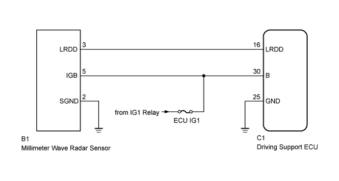
The driving support ECU sends information on steering angle and steering direction to the millimeter wave radar sensor. The millimeter wave radar sensor then sends information on the presence, distance, and relative speed of objects ahead to the driving support ECU. The driving support ECU sends this information to the ECM and performs cruise control.
| DTC No. | DTC Detection Condition | Trouble Area |
|---|---|---|
| U0235 | When the power switch is on (IG), a communication error between the millimeter wave radar sensor and the driving support ECU is detected for approx. 1 second. |
|
WIRING DIAGRAM
INSPECTION PROCEDURE
Note
-
When replacing the millimeter wave radar sensor with a new one, make sure to perform Adjust Millimeter Wave Radar Sensor Assembly Click here.
-
Confirm that the connector is securely connected, as a partially connected connector is suspected for the cause of this DTC.
PROCEDURE
-
CHECK HARNESS AND CONNECTOR (DRIVING SUPPORT ECU - MILLIMETER WAVE RADAR SENSOR)
-
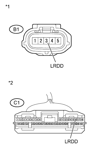
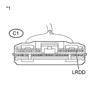
Text in Illustration *1 Front view of wire harness connector
(to Millimeter Wave Radar Sensor)
*2 Front view of wire harness connector
(to Driving Support ECU)
Disconnect the driving support ECU and millimeter wave radar sensor connectors.
-
Measure the resistance according to the value(s) in the table below.
Standard Resistance Tester Connection Condition Specified Condition C1-16 (LRDD) - B1-3 (LRDD) Always Below 1 Ω B1-3 (LRDD) - Body ground Always 10 kΩ or higher C1-16 (LRDD) - Body ground Always 10 kΩ or higher -
Reconnect the driving support ECU and millimeter wave radar sensor connectors.
NG 
REPAIR OR REPLACE HARNESS OR CONNECTOR (DRIVING SUPPORT ECU - MILLIMETER WAVE RADAR SENSOR)
OK 
-
-
CHECK MILLIMETER WAVE RADAR SENSOR (IGB VOLTAGE)
-
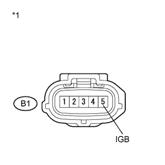
Text in Illustration *1 Front view of wire harness connector
(to Millimeter Wave Radar Sensor)
Disconnect the millimeter wave radar sensor connector.
-
Measure the voltage according to the value(s) in the table below.
Standard Voltage Tester Connection Switch Condition Specified Condition B1-5 (IGB) - Body ground Power switch on (IG) 11 to 14 V -
Reconnect the millimeter wave radar sensor connector.
NG
REPAIR OR REPLACE HARNESS OR CONNECTOR (IGB CIRCUIT)
OK
-
-
CHECK MILLIMETER WAVE RADAR SENSOR (SGND CIRCUIT)
-
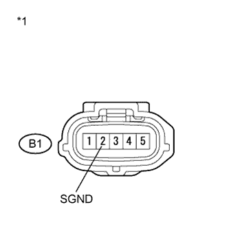
Text in Illustration *1 Front view of wire harness connector
(to Millimeter Wave Radar Sensor)
Disconnect the millimeter wave radar sensor connector.
-
Measure the resistance according to the value(s) in the table below.
Standard Resistance Tester Connection Switch Condition Specified Condition B1-2 (SGND) - Body ground Always Below 1 Ω -
Reconnect the millimeter wave radar sensor connector.
NG
REPAIR OR REPLACE HARNESS OR CONNECTOR (SGND CIRCUIT)
OK
-
-
CHECK MILLIMETER WAVE RADAR SENSOR (LRDD OUTPUT VOLTAGE)
-
Text in Illustration *1 Front view of wire harness connector
(to Driving Support ECU)
Disconnect the driving support ECU connector.
-
Turn the power switch on (IG).
-
Measure the voltage according to the value(s) in the table below.
Standard Voltage Tester Connection Switch Condition Specified Condition C1-16 (LRDD) - Body ground Power switch on (IG) 4.5 to 5.5 V -
Reconnect the driving support ECU connector.
NG
REPLACE MILLIMETER WAVE RADAR SENSOR Click here
OK
-
-
REPLACE DRIVING SUPPORT ECU
-
Replace the driving support ECU Click here.
NEXT
-
-
CHECK DTC OUTPUT
-
Clear the DTCs Click here.
-
Turn the cruise control main switch on.
-
Drive the vehicle at the required speed (45 km/h (27 mph) or higher).
-
Check if the same DTC is output Click here.
Result Result Proceed to DTC U0235 is not output A DTC U0235 is output B
B
REPLACE DRIVING SUPPORT ECU Click here
A 
END
-