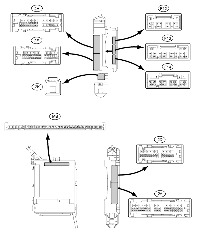
FRONT POWER SEAT CONTROL SYSTEM (w/ Memory) TERMINALS OF ECU

-
CHECK FRONT POWER SEAT SWITCH (LH)

-
Disconnect the a8 and a9 connectors from the front power seat switch LH.
-
Measure the voltage and resistance according to the value(s) in the table below.
Tech Tips
Measure the values on the wire harness side with the connector disconnected.
Tester Connection Wiring Color Terminal Description Condition Specified Condition a9-1 (GND) - Body ground W-B - Body ground Ground Always Below 1 Ω a9-6 (+B) - a9-1 (GND) LG - W-B Power source Always 11 to 14 V a8-12 (SYSB) - a9-1 (GND) GR - W-B System power source Always 11 to 14 V If the result is not as specified, there may be a malfunction in the wire harness.
-
Reconnect the a8 and a9 switch connectors.
-
Measure the voltage according to the value(s) in the table below.
Tester Connection Wiring Color Terminal Description Condition Specified Condition a9-2 (SLD+) - a9-1 (GND) L - W-B Sliding motor signal (forward) Slide switch off Below 1 V Slide switch on (Forward) 11 to 14 V a9-4 (SLD-) - a9-1 (GND) Y - W-B Sliding motor signal (rearward) Slide switch off Below 1 V Slide switch on (Rearward) 11 to 14 V a9-7 (FRV+) - a9-1 (GND) G - W-B Front vertical motor signal (upward) Front vertical switch off Below 1 V Front vertical switch on (Upward) 11 to 14 V a9-5 (FRV-) - a9-1 (GND) B - W-B Front vertical motor signal (downward) Front vertical switch off Below 1 V Front vertical switch on (Downward) 11 to 14 V a9-8 (LFT+) - a9-1 (GND) W - W-B Lifter motor signal (upward) Lifter switch off Below 1 V Lifter switch on (Upward) 11 to 14 V a9-11 (LFT-) - a9-1 (GND) V - W-B Lifter motor signal (downward) Lifter switch off Below 1 V Lifter switch on (Downward) 11 to 14 V a9-9 (RCL+) - a9-1 (GND) P - W-B Reclining motor signal (forward) Reclining switch off Below 1 V Reclining switch on (Forward) 11 to 14 V a9-12 (RCL-) - a9-1 (GND) SB - W-B Reclining motor signal (rearward) Reclining switch off Below 1 V Reclining switch on (Rearward) 11 to 14 V a8-4 (DBCL) - a9-1 (GND)*1 Y - W-B Buckle switch signal Always Below 1 V a8-4 (PBCL) - a9-1 (GND)*2 Tech Tips
*1: for LHD
*2: for RHD
If the result is not as specified, the front power seat switch may have a malfunction.
-
-
CHECK FRONT POWER SEAT SWITCH (RH)

-
Disconnect the Z25 and Z26 connectors from the front power seat switch RH.
-
Measure the voltage and resistance according to the value(s) in the table below.
Tech Tips
Measure the values on the wire harness side with the connector disconnected.
Tester Connection Wiring Color Terminal Description Condition Specified Condition Z26-1 (GND) - Body ground W-B - Body ground Ground Always Below 1 Ω Z26-6 (+B) - Z26-1 (GND) LG - W-B Power source Always 11 to 14 V Z25-12 (SYSB) - Z26-1 (GND) L - W-B System power source Always 11 to 14 V If the result is not as specified, there may be a malfunction in the wire harness.
-
Reconnect the Z25 and Z26 switch connectors.
-
Measure the voltage according to the value(s) in the table below.
Tester Connection Wiring Color Terminal Description Condition Specified Condition Z26-2 (SLD+) - Z26-1 (GND) L - W-B Sliding motor signal (forward) Slide switch off Below 1 V Slide switch on (Forward) 11 to 14 V Z26-4 (SLD-) - Z26-1 (GND) Y - W-B Sliding motor signal (rearward) Slide switch off Below 1 V Slide switch on (Rearward) 11 to 14 V Z26-7 (FRV+) - Z26-1 (GND) G - W-B Front vertical motor signal (upward) Front vertical switch off Below 1 V Front vertical switch on (Upward) 11 to 14 V Z26-5 (FRV-) - Z26-1 (GND) B - W-B Front vertical motor signal (downward) Front vertical switch off Below 1 V Front vertical switch on (Downward) 11 to 14 V Z26-8 (LFT+) - Z26-1 (GND) W - W-B Lifter motor signal (upward) Lifter switch off Below 1 V Lifter switch on (Upward) 11 to 14 V Z26-11 (LFT-) - Z26-1 (GND) V - W-B Lifter motor signal (downward) Lifter switch off Below 1 V Lifter switch on (Downward) 11 to 14 V Z26-9 (RCL+) - Z26-1 (GND) P - W-B Reclining motor signal (forward) Reclining switch off Below 1 V Reclining switch on (Forward) 11 to 14 V Z26-12 (RCL-) - Z26-1 (GND) SB - W-B Reclining motor signal (rearward) Reclining switch off Below 1 V Reclining switch on (Rearward) 11 to 14 V Z25-4 (DBCL) - Z26-1 (GND)*1 Y - W-B Buckle switch signal Always Below 1 V Z25-4 (PBCL) - Z26-1 (GND)*2 Tech Tips
*1: for RHD
*2: for LHD
If the result is not as specified, the front power seat switch may have a malfunction.
-
-
CHECK OUTER MIRROR CONTROL ECU ASSEMBLY LH

-
Disconnect the J3 connector from the outer mirror control ECU assembly LH.
-
Measure the voltage and resistance according to the value(s) in the table below.
Tester Connection Wiring Color Terminal Description Condition Specified Condition J3-7 (GND) - Body ground W-B - Body ground Ground Always Below 1 Ω J3-14 (BDR) - J3-7 (GND) Y - W-B Power source Always 11 to 14 V J3-5 (SIG) - J3-7 (GND) Y - W-B Power source (IG) Power switch off Below 1 V Power switch on (IG) 11 to 14 V J3-6 (CPUB) - J3-7 (GND) L - W-B Power source Always 11 to 14 V If the result is not as specified, there may be a malfunction in the wire harness.
-
Reconnect the J3 connector to the outer mirror control ECU assembly LH.
-
Measure the voltage according to the value(s) in the table below.
Tester Connection Wiring Color Terminal Description Condition Specified Condition J3-4 (M3) - J3-13 (MSWE) R - BR M3 switch signal for seat memory switch M3 switch on 11 to 14 V M3 switch off Below 1 V J3-3 (M2) - J3-13 (MSWE) V - BR M2 switch signal for seat memory switch M2 switch on 11 to 14 V M2 switch off Below 1 V J3-2 (M1) - J3-13 (MSWE) G - BR M1 switch signal for seat memory switch M1 switch on 11 to 14 V M1 switch off Below 1 V J3-1 (MM) - J3-13 (MSWE) W - BR SET switch signal for seat memory switch SET switch on 11 to 14 V SET switch off Below 1 V If the result is not as specified, the outer mirror control ECU assembly LH may have a malfunction.
-
-
CHECK OUTER MIRROR CONTROL ECU ASSEMBLY RH

-
Disconnect the I4 connector from the outer mirror control ECU assembly RH.
-
Measure the voltage and resistance according to the value(s) in the table below.
Tester Connection Wiring Color Terminal Description Condition Specified Condition I4-7 (GND) - Body ground W-B - Body ground Ground Always Below 1 Ω I4-14 (BDR) - I4-7 (GND) G - W-B Power source Always 11 to 14 V I4-5 (SIG) - I4-7 (GND) GR - W-B Power source (IG) Power switch off Below 1 V Power switch on (IG) 11 to 14 V I4-6 (CPUB) - I4-7 (GND) P - W-B Power source Always 11 to 14 V If the result is not as specified, there may be a malfunction in the wire harness.
-
Reconnect the I4 connector to the outer mirror control ECU assembly RH.
-
Measure the voltage according to the value(s) in the table below.
Tester Connection Wiring Color Terminal Description Condition Specified Condition I4-4 (M3) - I4-13 (MSWE) R - BR M3 switch signal for seat memory switch M3 switch on 11 to 14 V M3 switch off Below 1 V I4-3 (M2) - I4-13 (MSWE) V - BR M2 switch signal for seat memory switch M2 switch on 11 to 14 V M2 switch off Below 1 V I4-2 (M1) - I4-13 (MSWE) G - BR M1 switch signal for seat memory switch M1 switch on 11 to 14 V M1 switch off Below 1 V I4-1 (MM) - I4-13 (MSWE) L - BR SET switch signal for seat memory switch SET switch on 11 to 14 V SET switch off Below 1 V If the result is not as specified, the outer mirror control ECU assembly RH may have a malfunction.
-
-
CHECK MAIN BODY ECU (MULTIPLEX NETWORK BODY ECU)
-
Disconnect the 2F, 2K and 2D connectors from the instrument panel junction block assembly.
-
Measure the voltage and resistance according to the value(s) in the table below.
Tester Connection Wiring Color Terminal Description Condition Specified Condition 2F-40 (BECU) - Body ground G - Body ground Power source Always 11 to 14 V 2K-1 (IG) - Body ground B - Body ground Power source (IG) Power switch on (IG) 11 to 14 V Power switch off Below 1 V 2D-6 (GND1) - Body ground BR - Body ground Body ground Always Below 1 Ω If the result is not as specified, there may be a malfunction in the wire harness.
-
Reconnect the 2F, 2K and 2D instrument panel junction block assembly connectors.
-
Measure the voltage according to the value(s) in the table below.
Tester Connection Wiring Color Terminal Description Condition Specified Condition 2H-26 (FLCY) - Body ground B - Body ground Front door courtesy light switch assembly signal Driver side door closed 10 to 14 V Driver side door open Below 1 V
-