PRE-CRASH SAFETY SYSTEM, Diagnostic DTC:B2075

| DTC Code | DTC Name |
|---|---|
| B2075 | Passenger Side Seat Belt Buckle Switch Circuit Malfunction |
DESCRIPTION
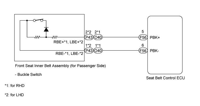
This DTC is stored when there is a short or open in the front seat inner belt buckle switch circuit (for passenger side).
| DTC No. | DTC Detection Condition | Trouble Area |
|---|---|---|
| B2075 | Open or short in front seat inner belt (buckle switch) circuit |
|
WIRING DIAGRAM
INSPECTION PROCEDURE
PROCEDURE
-
CHECK HARNESS AND CONNECTOR (FRONT SEAT INNER BELT ASSEMBLY - SEAT BELT CONTROL ECU)
-
Disconnect the front seat inner belt assembly connector.
-
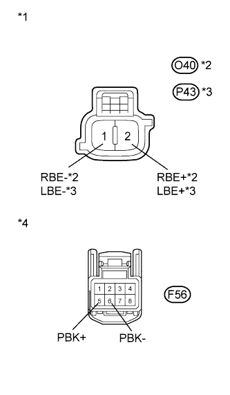
Text in Illustration *1 Front view of wire harness connector
(to Front Seat Inner Belt Assembly)
*2 RHD *3 LHD *4 Front view of wire harness connector
(to Seat Belt Control ECU)
Disconnect the seat belt control ECU connector.
-
Measure the resistance according to the value(s) in the table below.
Standard Resistance for RHD Tester Connection Condition Specified Condition F56-5 (PBK+) - O40-2 (RBE+) Always Below 1 Ω F56-6 (PBK-) - O40-1 (RBE-) Always Below 1 Ω F56-5 (PBK+) or O40-2 (RBE+) - Body ground Always 10 kΩ or higher F56-6 (PBK-) or O40-1 (RBE) - Body ground Always 10 kΩ or higher for LHD Tester Connection Condition Specified Condition F56-5 (PBK+) - P43-2 (LBE+) Always Below 1 Ω F56-6 (PBK-) - P43-1 (LBE-) Always Below 1 Ω F56-5 (PBK+) or P43-2 (LBE+) - Body ground Always 10 kΩ or higher F56-6 (PBK-) or P43-1 (LBE-) - Body ground Always 10 kΩ or higher -
Reconnect the seat belt control ECU connector.
-
Reconnect the front seat inner belt assembly connector.
NG 
REPAIR OR REPLACE HARNESS OR CONNECTOR (FRONT SEAT INNER BELT ASSEMBLY - SEAT BELT CONTROL ECU)
OK 
-
-
CHECK SEAT BELT CONTROL ECU
-
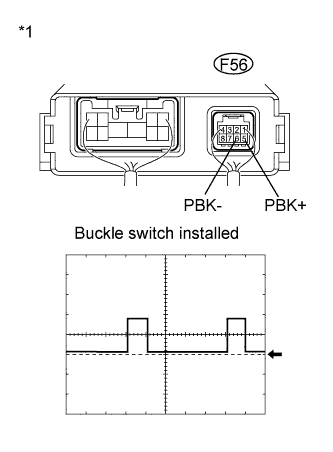
Text in Illustration *1 Component without harness connected
Seat Belt Control ECU
Fasten the passenger side seat belt.
-
Turn the power switch on (IG).
-
Using an oscilloscope, check the waveform of the seat belt control ECU between the connector terminals.
Tech Tips
Voltage is only output for 10 ms of a 100 ms cycle.
Item Contents Terminal F56-5 (PBK+)
F56-6 (PBK-)
Tool setting 2V/DIV, 20ms/DIV Vehicle Condition Power switch on (IG) OK Approximately 5 V
NG
REPLACE FRONT SEAT INNER BELT ASSEMBLY (for Passenger Side)
OK 
REPLACE SEAT BELT CONTROL ECU Click here
-