FRONT PASSENGER AIRBAG ASSEMBLY INSTALLATION

-
INSTALL INSTRUMENT PANEL WIRE ASSEMBLY
-
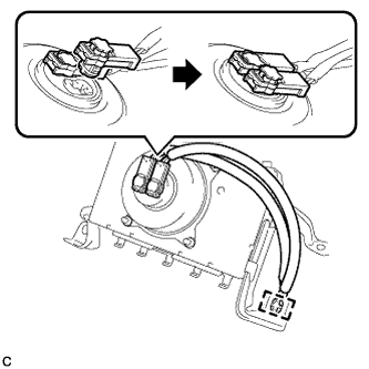
Connect the 2 airbag connectors.
Note
-
When connecting any airbag connector, take care not to damage the airbag wire harness.
-
Be sure to only connect the connectors to each corresponding color.
-
-
Push in the lock to install the airbag connector.
-
Engage the clamp to install the instrument panel wire assembly to the front passenger airbag assembly.
-
-
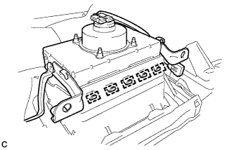
INSTALL FRONT PASSENGER AIRBAG ASSEMBLY
-
Engage the 5 hooks.
-
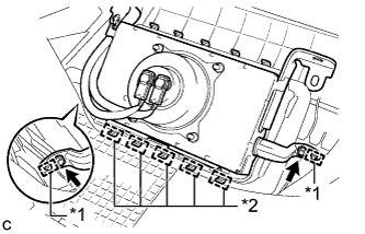
Push the front passenger airbag assembly to engage the 5 hooks.
-
Engage the 2 pins.
-
Install the 2 screws to install the front passenger airbag assembly.
Text in Illustration *1 Pin *2 Hook
-
-
INSTALL INSTRUMENT PANEL SAFETY PAD ASSEMBLY
-
Engage the 5 claws and temporarily install the instrument panel safety pad assembly as shown in the illustration.
CAUTION:
Leaks of cold air may result in condensation in the instrument panel. This condensation may cause short circuits in electrical parts. Be sure to insert and fit the No. 1 heater to register duct and the No. 4 heater to register duct tightly to the No. 1 air duct sub-assembly.
Note
-
Do not damage the instrument panel safety pad assembly.
-
Do not allow the wire harnesses to interfere with the surrounding parts.
-
-
Install the 2 clips.
-
Install the 6 bolts <C> and nut <H> or <I>.
-
Install the 2 passenger airbag bolts <A> or <B>.
- Torque:
- 20 N*m { 204 kgf*cm, 15 ft.*lbf }
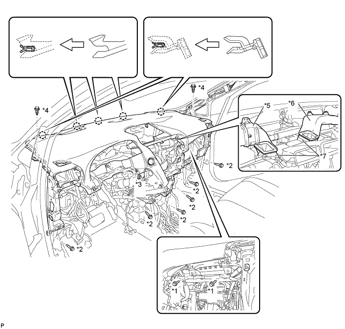
Text in Illustration *1 Passenger Airbag Bolt <A> or <B> *2 Bolt <C> *3 Nut <H> or <I> *4 Clip *5 No. 1 Heater To Register Duct *6 No. 4 Heater To Register Duct *7 No. 1 Air Duct Sub-assembly - - -
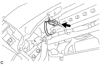
Engage the 2 claws to connect the room temperature sensor.
-
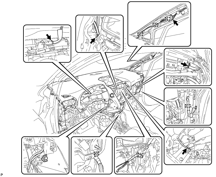
Engage each clamp.
-
Connect each connector.
-
-
CONNECT INSTRUMENT PANEL WIRE ASSEMBLY
-
Check that the power switch is off.
-
Check that the cable is disconnected from the negative (-) battery terminal.
CAUTION:
Wait at least 90 seconds after disconnecting the cable from the negative (-) battery terminal to disable the SRS system.
-
Connect the connector.
Note
When connecting any airbag connector, take care not to damage the airbag wire harness.
-
-
INSTALL NO. 1 CONSOLE BOX DUCT
Tech Tips
Refer to the procedure from Install No. 1 Console Box Duct Click here.
-
PERFORM DIAGNOSTIC SYSTEM CHECK
-
Perform a diagnostic system check Click here.
-