SPIRAL CABLE REMOVAL

-
PRECAUTION
CAUTION:
Be sure to read Precaution thoroughly before servicing Click here.
Note
w/ Navigation System for HDD:
After the power switch is turned off, the display and navigation module display (HDD navigation system) records various types of memory and settings. As a result, after turning the power switch off, make sure to wait for the time specified in the following table before disconnecting the cable from the negative (-) battery terminal.
Waiting Time before Disconnecting Cable from Negative (-) Battery Terminal Specification Waiting Time w/o Telematics Transceiver 60 sec. w/ Telematics Transceiver 120 sec. -
ALIGN FRONT WHEELS FACING STRAIGHT AHEAD
-
REMOVE REAR DECK FLOOR BOX
-

Remove the 3 clips and the rear deck floor box.
-
-
DISCONNECT CABLE FROM NEGATIVE BATTERY TERMINAL
-
Disable the auto away/return function by changing the customize parameter Click here.
Note
Record the current customize parameter setting (whether the auto away/return function is enabled or disabled) in order to restore the current setting after finishing this operation.
Tech Tips
Performing the above operation disables the auto away/return function when the power switch is turned off.
-
Turn the power switch on (IG). Operate the tilt and telescopic switch to fully extend and lower the steering column assembly.
-
Turn the power switch off and disconnect the cable from the negative (-) battery terminal.
CAUTION:
Wait at least 90 seconds after disconnecting the cable from the negative (-) battery terminal to disable the SRS system.
Note
When disconnecting the cable, some systems need to be initialized after the cable is reconnected Click here.
-
-
REMOVE LOWER NO. 3 STEERING WHEEL COVER
-
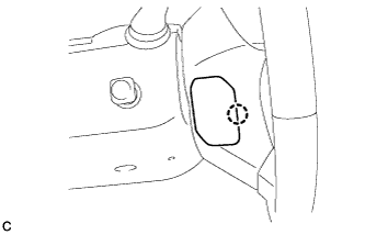
Using a screwdriver with its tip wrapped with protective tape, disengage the claw to remove the lower No. 3 steering wheel cover.
-
-
REMOVE LOWER NO. 2 STEERING WHEEL COVER
-
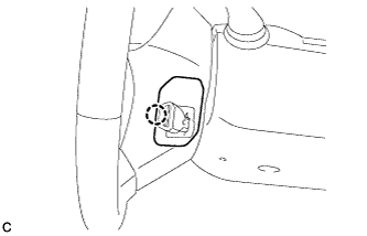
Using a screwdriver with its tip wrapped with protective tape, disengage the claw to remove the lower No. 2 steering wheel cover.
-
-
REMOVE STEERING PAD
CAUTION:
When storing the steering pad, keep the airbag deployment side facing upward.
-
Check that the power switch is off.
-
Check that the cable is disconnected from the negative (-) battery terminal.
CAUTION:
Wait at least 90 seconds after disconnecting the cable from the negative (-) battery terminal to disable the SRS system.
-
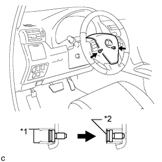
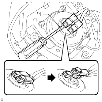
Text in Illustration *1 Screw Case *2 "TORX" Screw Using a T30 "TORX" socket wrench, loosen the 2 "TORX" screws until the groove along the screw circumference catches on the screw case.
-
Text in Illustration *1 Protective Tape Pull out the steering pad from the steering wheel assembly and support the steering pad with one hand as shown in the illustration.
Note
When removing the steering pad, do not pull the airbag wire harness.
-
Disconnect the horn connector from the steering pad.
-
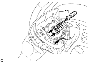
Using a screwdriver with its tip wrapped with protective tape, release the airbag connector locks.
-
Text in Illustration *1 Protective Tape Disconnect the airbag connectors to remove the steering pad as shown in the illustration.
Note
When disconnecting any airbag connector, take care not to damage the airbag wire harness.
-
-
REMOVE STEERING WHEEL ASSEMBLY
-
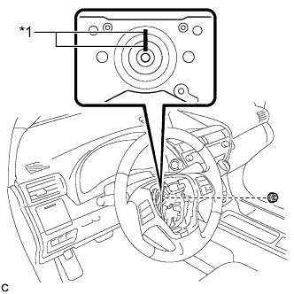
Text in Illustration *1 Matchmark Remove the steering wheel assembly set nut.
-
Put matchmarks on the steering wheel assembly and steering main shaft.
-
Disconnect the connectors from the spiral cable.
-
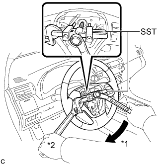
Text in Illustration *1 Turn *2 Hold Using SST, remove the steering wheel assembly.
- SST
- 09950-50013 ( 09951-05010, 09952-05010, 09953-05020, 09954-05070 )
Note
Apply a small amount of grease to the threads and tip of SST (09953-05020) before use.
-
-
REMOVE STEERING COLUMN COVER
Note
Removing the lower steering column cover in the incorrect order will cause the parts to break.
-
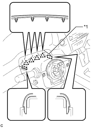
Text in Illustration *1 Instrument Panel Cluster Finish Panel Disengage the 4 clips and 2 guides to separate the instrument panel cluster finish panel from the upper steering column cover.
-
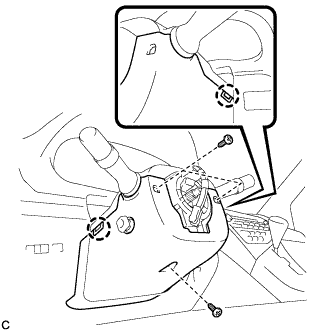
Remove the 3 screws.
-
Disengage the 2 claws to remove the lower steering column cover.
Note
Do not damage the tilt and telescopic switch.
-
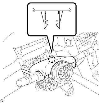
Disengage the claw to remove the upper steering column cover.
-
-
REMOVE SPIRAL CABLE WITH SENSOR SUB-ASSEMBLY
Note
-
Do not replace the spiral cable with the battery connected and the power switch on (IG).
-
Do not rotate the spiral cable with the battery connected and the power switch on (IG).
-
Ensure that the steering wheel is installed and aligned straight when inspecting the steering sensor.
-
Do not remove the steering sensor from the spiral cable.
-
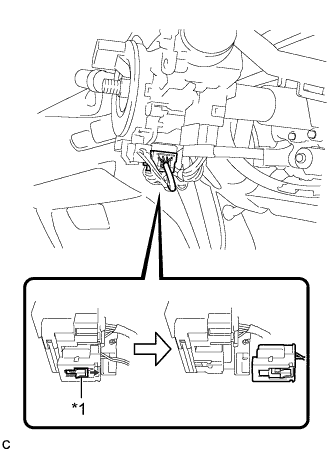
Text in Illustration *1 Slider Slide the slider to release the lock, and then disconnect the yellow airbag connector from the spiral cable with sensor sub-assembly.
Note
When disconnecting any airbag connector, take care not to damage the airbag wire harness.
-
Disconnect the other connector from the spiral cable with sensor sub-assembly.
-
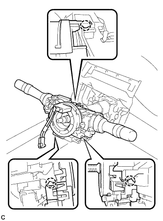
Disengage the 3 claws and remove the spiral cable with sensor sub-assembly.
-