AIRBAG SYSTEM, Diagnostic DTC:B1660/43

| DTC Code | DTC Name |
|---|---|
| B1660/43 | Passenger Airbag ON/OFF Indicator Circuit Malfunction |
DESCRIPTION
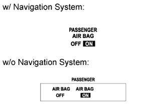
The passenger airbag ON/OFF indicator circuit consists of the center airbag sensor assembly and passenger airbag ON/OFF indicator.
The passenger airbag ON/OFF indicator indicates the operation condition of the front passenger airbag and front passenger side knee airbag.
DTC B1660/43 is recorded when a malfunction is detected in the passenger airbag ON/OFF indicator circuit.
| DTC No. | DTC Detection Condition | Trouble Area |
|---|---|---|
| B1660/43 |
|
|
-
*1: w/ Navigation System
-
*2: w/o Navigation System
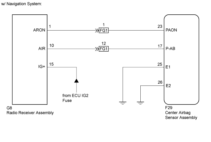
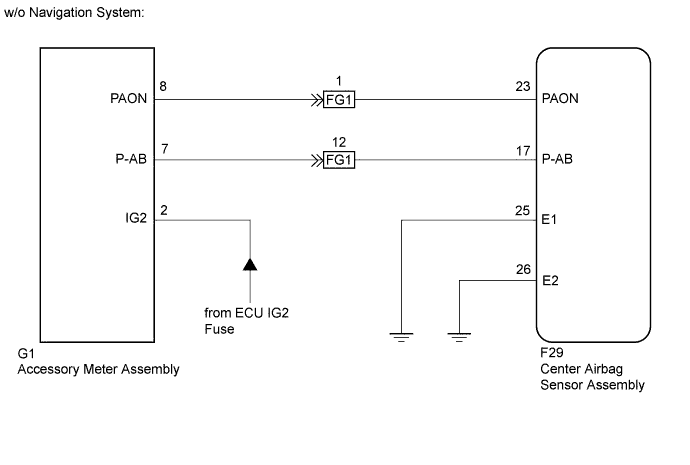
WIRING DIAGRAM
INSPECTION PROCEDURE
PROCEDURE
-
CHECK PASSENGER AIRBAG ON/OFF INDICATOR CONDITION
-
Turn the power switch on (IG).
-
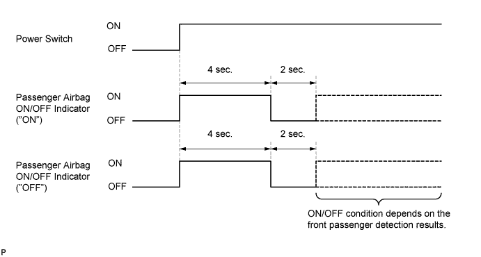
Check the passenger airbag ON/OFF indicator operation.
Tech Tips
Refer to the normal condition of the passenger airbag ON/OFF indicator Click here.
Result ON/OFF Indicator Illumination Proceed to Always ON A OFF B
B 
CHECK CONNECTORS Click here
A 
-
-
CHECK CONNECTORS
-
Turn the power switch off.
-
Disconnect the cable from the negative (-) battery terminal.
Note
Wait at least 90 seconds after disconnecting the cable from the negative (-) battery terminal to disable the SRS system.
-
Check that the connectors are properly connected to the center airbag sensor assembly and radio receiver assembly*1 or accessory meter assembly*2. Also check that the connectors that link the instrument panel wire and No. 2 instrument panel wire are properly connected.
-
*1: w/ Navigation System
-
*2: w/o Navigation System
OK The connectors are properly connected. Tech Tips
If the connectors are not connected securely, reconnect the connectors and proceed to the next inspection.
-
-
Disconnect the connectors from the center airbag sensor assembly and radio receiver assembly*1 or accessory meter assembly*2. Also disconnect the connectors that link the instrument panel wire and No. 2 instrument panel wire.
-
*1: w/ Navigation System
-
*2: w/o Navigation System
-
-
Check that the terminals of connectors are not damaged.
OK The terminals are not deformed or damaged.
NG 
REPLACE WIRE HARNESS
OK
-
-
CHECK PASSENGER AIRBAG ON/OFF INDICATOR
-
Connect the connectors that link the instrument panel wire and No. 2 instrument panel wire.
-
Connect the connector to the radio receiver assembly*1 or accessory meter assembly*2.
-
*1: w/ Navigation System
-
*2: w/o Navigation System
-
-
Connect the cable to the negative (-) battery terminal.
-
Turn the power switch on (IG).
-
Check the passenger airbag ON/OFF indicator operation.
OK The passenger airbag ON/OFF indicator does not come on.
NG
CHECK PASSENGER AIRBAG ON/OFF INDICATOR CIRCUIT (OPEN) Click here
OK
-
-
CHECK CENTER AIRBAG SENSOR ASSEMBLY
-
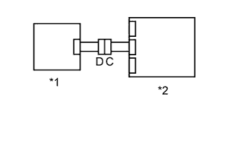
Text in Illustration *1 Radio Receiver Assembly*1 or Accessory Meter Assembly*2 *2 Center Airbag Sensor Assembly Connect the connector to the center airbag sensor assembly.
-
Connect the cable to the negative (-) battery terminal.
-
Turn the power switch on (IG), and wait for at least 60 seconds.
-
Clear the DTCs stored in the memory Click here.
-
Turn the power switch off.
-
Turn the power switch on (IG), and wait for at least 60 seconds.
-
Check for DTCs Click here.
OK DTC B1660/43 is not output.
-
*1: w/ Navigation System
-
*2: w/o Navigation System
Tech Tips
Codes other than DTC B1660/43 may be output at this time, but they are not related to this check.
-
NG
REPLACE CENTER AIRBAG SENSOR ASSEMBLY Click here
OK 
USE SIMULATION METHOD TO CHECK Click here
-
-
CHECK PASSENGER AIRBAG ON/OFF INDICATOR CIRCUIT (OPEN)
-
Turn the power switch off.
-
Disconnect the cable from the negative (-) battery terminal.
Note
Wait at least 90 seconds after disconnecting the cable from the negative (-) battery terminal to disable the SRS system.
-
Connect the connectors that link the instrument panel wire and No. 2 instrument panel wire.
-
Disconnect the connector from the radio receiver assembly*1 or accessory meter assembly*2.
-
*1: w/ Navigation System
-
*2: w/o Navigation System
-
-
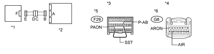
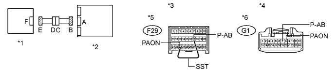
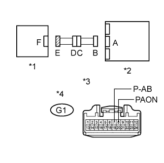
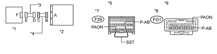
Using SST, connect terminals 23 (PAON) and 17 (P-AB) of connector B.
Note
Do not forcibly insert SST into the terminals of the connector when connecting the wire.
- SST
- 09843-18040
-
w/ Navigation System:
-
Measure the resistance according to the value(s) in the table below.
Standard Resistance Tester Connection Condition Specified Condition G8-1 (ARON) - G8-10 (AIR) Always Below 1 Ω Text in Illustration *1 Radio Receiver Assembly *2 Center Airbag Sensor Assembly *3 Front view of wire harness connector
(to Center Airbag Sensor Assembly)
*4 Front view of wire harness connector
(to Radio Receiver Assembly)
*5 Connector B *6 Connector E
-
-
w/o Navigation System:
-
Measure the resistance according to the value(s) in the table below.
Standard Resistance Tester Connection Condition Specified Condition G1-8 (PAON) - G1-7 (P-AB) Always Below 1 Ω Text in Illustration *1 Accessory Meter Assembly *2 Center Airbag Sensor Assembly *3 Front view of wire harness connector
(to Center Airbag Sensor Assembly)
*4 Front view of wire harness connector
(to Accessory Meter Assembly)
*5 Connector B *6 Connector E
-
NG
CHECK INSTRUMENT PANEL WIRE (OPEN) Click here
OK
-
-
CHECK PASSENGER AIRBAG ON/OFF INDICATOR CIRCUIT (SHORT)
-
Disconnect SST from connector B.
-
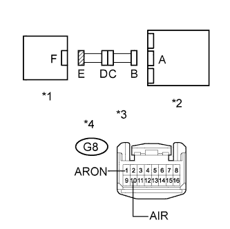
Text in Illustration *1 Radio Receiver Assembly *2 Center Airbag Sensor Assembly *3 Front view of wire harness connector
(to Radio Receiver Assembly)
*4 Connector E w/ Navigation System:
-
Measure the resistance according to the value(s) in the table below.
Standard Resistance Tester Connection Condition Specified Condition G8-1 (ARON) - G8-10 (AIR) Always 1 MΩ or higher
-
-
Text in Illustration *1 Accessory Meter Assembly *2 Center Airbag Sensor Assembly *3 Front view of wire harness connector
(to Accessory Meter Assembly)
*4 Connector E w/o Navigation System:
-
Measure the resistance according to the value(s) in the table below.
Standard Resistance Tester Connection Condition Specified Condition G1-8 (PAON) - G1-7 (P-AB) Always 1 MΩ or higher
-
NG
CHECK INSTRUMENT PANEL WIRE (SHORT) Click here
OK
-
-
CHECK PASSENGER AIRBAG ON/OFF INDICATOR CIRCUIT (SHORT TO GROUND)
-
Text in Illustration *1 Radio Receiver Assembly *2 Center Airbag Sensor Assembly *3 Front view of wire harness connector
(to Radio Receiver Assembly)
*4 Connector E w/ Navigation System:
-
Measure the resistance according to the value(s) in the table below.
Standard Resistance Tester Connection Condition Specified Condition G8-1 (ARON) - Body ground Always 1 MΩ or higher G8-10 (AIR) - Body ground Always 1 MΩ or higher
-
-
Text in Illustration *1 Accessory Meter Assembly *2 Center Airbag Sensor Assembly *3 Front view of wire harness connector
(to Accessory Meter Assembly)
*4 Connector E w/o Navigation System:
-
Measure the resistance according to the value(s) in the table below.
Standard Resistance Tester Connection Condition Specified Condition G1-8 (PAON) - Body ground Always 1 MΩ or higher G1-7 (P-AB) - Body ground Always 1 MΩ or higher
-
NG
CHECK INSTRUMENT PANEL WIRE (SHORT TO GROUND) Click here
OK
-
-
CHECK PASSENGER AIRBAG ON/OFF INDICATOR CIRCUIT (SHORT TO B+)
-
Connect the cable to the negative (-) battery terminal.
-
Turn the power switch on (IG).
-
Text in Illustration *1 Radio Receiver Assembly *2 Center Airbag Sensor Assembly *3 Front view of wire harness connector
(to Radio Receiver Assembly)
*4 Connector E w/ Navigation System:
-
Measure the voltage according to the value(s) in the table below.
Standard Voltage Tester Connection Switch Condition Specified Condition G8-1 (ARON) - Body ground Power switch on (IG) Below 1 V G8-10 (AIR) - Body ground Power switch on (IG) Below 1 V
-
-
Text in Illustration *1 Accessory Meter Assembly *2 Center Airbag Sensor Assembly *3 Front view of wire harness connector
(to Accessory Meter Assembly)
*4 Connector E w/o Navigation System:
-
Measure the voltage according to the value(s) in the table below.
Standard Voltage Tester Connection Switch Condition Specified Condition G1-8 (PAON) - Body ground Power switch on (IG) Below 1 V G1-7 (P-AB) - Body ground Power switch on (IG) Below 1 V
-
NG
CHECK INSTRUMENT PANEL WIRE (SHORT TO B+) Click here
OK
REPLACE CENTER AIRBAG SENSOR ASSEMBLY Click here
-
-
CHECK CONNECTORS
-
Turn the power switch off.
-
Disconnect the cable from the negative (-) battery terminal.
Note
Wait at least 90 seconds after disconnecting the cable from the negative (-) battery terminal to disable the SRS system.
-
Check that the connectors are properly connected to the center airbag sensor assembly and radio receiver assembly*1 or accessory meter assembly*2. Also check that the connectors that link the instrument panel wire and No. 2 instrument panel wire are properly connected.
-
*1: w/ Navigation System
-
*2: w/o Navigation System
OK The connectors are properly connected. Tech Tips
If the connectors are not connected securely, reconnect the connectors and proceed to the next inspection.
-
-
Disconnect the connectors from the center airbag sensor assembly and radio receiver assembly*1 or accessory meter assembly*2. Also disconnect the connectors that link the instrument panel wire and No. 2 instrument panel wire.
-
*1: w/ Navigation System
-
*2: w/o Navigation System
-
-
Check that the terminals of connectors are not damaged.
OK The terminals are not deformed or damaged.
NG
REPLACE WIRE HARNESS
OK
-
-
CHECK PASSENGER AIRBAG ON/OFF INDICATOR CIRCUIT (OPEN)
-
Connect the connectors that link the instrument panel wire and No. 2 instrument panel wire.
-
Using SST, connect terminals 23 (PAON) and 17 (P-AB) of connector B.
Note
Do not forcibly insert SST into the terminals of the connector when connecting the wire.
- SST
- 09843-18040
-
w/ Navigation System:
-
Measure the resistance according to the value(s) in the table below.
Standard Resistance Tester Connection Condition Specified Condition G8-1 (ARON) - G8-10 (AIR) Always Below 1 Ω Text in Illustration *1 Radio Receiver Assembly *2 Center Airbag Sensor Assembly *3 Front view of wire harness connector
(to Center Airbag Sensor Assembly)
*4 Front view of wire harness connector
(to Radio Receiver Assembly)
*5 Connector B *6 Connector E
-
-
w/o Navigation System:
-
Measure the resistance according to the value(s) in the table below.
Standard Resistance Tester Connection Condition Specified Condition G1-8 (PAON) - G1-7 (P-AB) Always Below 1 Ω Text in Illustration *1 Accessory Meter Assembly *2 Center Airbag Sensor Assembly *3 Front view of wire harness connector
(to Center Airbag Sensor Assembly)
*4 Front view of wire harness connector
(to Accessory Meter Assembly)
*5 Connector B *6 Connector E
-
NG
CHECK INSTRUMENT PANEL WIRE (OPEN) Click here
OK
-
-
CHECK PASSENGER AIRBAG ON/OFF INDICATOR CIRCUIT (SHORT)
-
Disconnect SST from connector B.
-
Text in Illustration *1 Radio Receiver Assembly *2 Center Airbag Sensor Assembly *3 Front view of wire harness connector
(to Radio Receiver Assembly)
*4 Connector E w/ Navigation System:
-
Measure the resistance according to the value(s) in the table below.
Standard Resistance Tester Connection Condition Specified Condition G8-1 (ARON) - G8-10 (AIR) Always 1 MΩ or higher
-
-
Text in Illustration *1 Accessory Meter Assembly *2 Center Airbag Sensor Assembly *3 Front view of wire harness connector
(to Accessory Meter Assembly)
*4 Connector E w/o Navigation System:
-
Measure the resistance according to the value(s) in the table below.
Standard Resistance Tester Connection Condition Specified Condition G1-8 (PAON) - G1-7 (P-AB) Always 1 MΩ or higher
-
NG
CHECK INSTRUMENT PANEL WIRE (SHORT) Click here
OK
-
-
CHECK PASSENGER AIRBAG ON/OFF INDICATOR CIRCUIT (SHORT TO GROUND)
-
Text in Illustration *1 Radio Receiver Assembly *2 Center Airbag Sensor Assembly *3 Front view of wire harness connector
(to Radio Receiver Assembly)
*4 Connector E w/ Navigation System:
-
Measure the resistance according to the value(s) in the table below.
Standard Resistance Tester Connection Condition Specified Condition G8-1 (ARON) - Body ground Always 1 MΩ or higher G8-10 (AIR) - Body ground Always 1 MΩ or higher
-
-
Text in Illustration *1 Accessory Meter Assembly *2 Center Airbag Sensor Assembly *3 Front view of wire harness connector
(to Accessory Meter Assembly)
*4 Connector E w/o Navigation System:
-
Measure the resistance according to the value(s) in the table below.
Standard Resistance Tester Connection Condition Specified Condition G1-8 (PAON) - Body ground Always 1 MΩ or higher G1-7 (P-AB) - Body ground Always 1 MΩ or higher
-
NG
CHECK INSTRUMENT PANEL WIRE (SHORT TO GROUND) Click here
OK
-
-
CHECK PASSENGER AIRBAG ON/OFF INDICATOR CIRCUIT (SHORT TO B+)
-
Connect the cable to the negative (-) battery terminal.
-
Turn the power switch on (IG).
-
Text in Illustration *1 Radio Receiver Assembly *2 Center Airbag Sensor Assembly *3 Front view of wire harness connector
(to Radio Receiver Assembly)
*4 Connector E w/ Navigation System:
-
Measure the voltage according to the value(s) in the table below.
Standard Voltage Tester Connection Switch Condition Specified Condition G8-1 (ARON) - Body ground Power switch on (IG) Below 1 V G8-10 (AIR) - Body ground Power switch on (IG) Below 1 V
-
-
Text in Illustration *1 Accessory Meter Assembly *2 Center Airbag Sensor Assembly *3 Front view of wire harness connector
(to Accessory Meter Assembly)
*4 Connector E w/o Navigation System:
-
Measure the voltage according to the value(s) in the table below.
Standard Voltage Tester Connection Switch Condition Specified Condition G1-8 (PAON) - Body ground Power switch on (IG) Below 1 V G1-7 (P-AB) - Body ground Power switch on (IG) Below 1 V
-
NG
CHECK INSTRUMENT PANEL WIRE (SHORT TO B+) Click here
OK
-
-
CHECK PASSENGER AIRBAG ON / OFF INDICATOR (SOURCE VOLTAGE)
-
Turn the power switch on (IG).
-
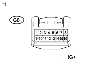
Text in Illustration *1 Front view of wire harness connector
(to Radio Receiver Assembly)
w/ Navigation System:
-
Measure the voltage according to the value(s) in the table below.
Standard Voltage Tester Connection Switch Condition Specified Condition G8-15 (IG+) - Body ground Power switch on (IG) 10 to 14 V Result Result Proceed to OK A NG B
-
-
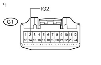
Text in Illustration *1 Front view of wire harness connector
(to Accessory Meter Assembly)
w/o Navigation System:
-
Measure the voltage according to the value(s) in the table below.
Standard Voltage Tester Connection Switch Condition Specified Condition G1-2 (IG2) - Body ground Power switch on (IG) 10 to 14 V Result Result Proceed to OK A NG C
-
B
REPLACE WIRE HARNESS (RADIO RECEIVER ASSEMBLY - BATTERY) OR BATTERY
C
REPLACE WIRE HARNESS (ACCESSORY METER ASSEMBLY - BATTERY) OR BATTERY
A
-
-
CHECK PASSENGER AIRBAG ON/OFF INDICATOR
-
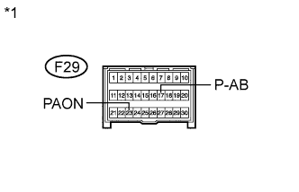
Text in Illustration *1 Front view of wire harness connector
(to Center Airbag Sensor Assembly)
Turn the power switch off.
-
Disconnect the cable from the negative (-) battery terminal.
Note
Wait at least 90 seconds after disconnecting the cable from the negative (-) battery terminal to disable the SRS system.
-
Connect the connector to the radio receiver assembly*1 or accessory meter assembly*2.
-
*1: w/ Navigation System
-
*2: w/o Navigation System
-
-
Connect the cable to the negative (-) battery terminal.
-
Turn the power switch on (IG).
-
Check the indicator according to the conditions in the table below.
Result Tester Connection Switch Condition Passenger Airbag ON/OFF Indicator F29-23 (PAON) - Body ground Power switch on (IG) "ON" comes on F29-17 (P-AB) - Body ground Power switch on (IG) "OFF" comes on Result Result Proceed to OK A NG (w/ Navigation System) B NG (w/o Navigation System) C
B
REPLACE RADIO RECEIVER ASSEMBLY Click here
C
REPLACE ACCESSORY METER ASSEMBLY Click here
A
-
-
CHECK CENTER AIRBAG SENSOR ASSEMBLY
-
Text in Illustration *1 Radio Receiver Assembly*1 or Accessory Meter Assembly*2 *2 Center Airbag Sensor Assembly Turn the power switch off.
-
Disconnect the cable from the negative (-) battery terminal.
Note
Wait at least 90 seconds after disconnecting the cable from the negative (-) battery terminal to disable the SRS system.
-
Connect the connector to the center airbag sensor assembly.
-
Connect the cable to the negative (-) battery terminal.
-
Turn the power switch on (IG), and wait for at least 60 seconds.
-
Clear the DTCs stored in the memory Click here.
-
Turn the power switch off.
-
Turn the power switch on (IG), and wait for at least 60 seconds.
-
Check for DTCs Click here.
OK DTC B1660/43 is not output.
-
*1: w/ Navigation System
-
*2: w/o Navigation System
Tech Tips
Codes other than DTC B1660/43 may be output at this time, but they are not related to this check.
-
NG
REPLACE CENTER AIRBAG SENSOR ASSEMBLY Click here
OK
USE SIMULATION METHOD TO CHECK Click here
-
-
CHECK INSTRUMENT PANEL WIRE (OPEN)
-
Disconnect the instrument panel wire from the No. 2 instrument panel wire.
Tech Tips
SST has already been inserted into connector B.
-
Measure the resistance according to the value(s) in the table below.
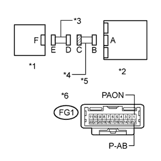
Standard Resistance Tester Connection Condition Specified Condition FG1-1 (PAON) - FG1-12 (P-AB) Always Below 1 Ω Text in Illustration *1 Radio Receiver Assembly*1 or Accessory Meter Assembly*2 *2 Center Airbag Sensor Assembly *3 No. 2 Instrument Panel Wire *4 Instrument Panel Wire *5 Front view of wire harness connector
(to Center Airbag Sensor Assembly)
*6 Front view of wire harness connector
(to No. 2 Instrument Panel Wire)
*7 Connector B *8 Connector C
-
*1: w/ Navigation System
-
*2: w/o Navigation System
-
NG
REPLACE INSTRUMENT PANEL WIRE
OK
REPLACE NO. 2 INSTRUMENT PANEL WIRE
-
-
CHECK INSTRUMENT PANEL WIRE (SHORT)
-
Text in Illustration *1 Radio Receiver Assembly*1 or Accessory Meter Assembly*2 *2 Center Airbag Sensor Assembly *3 No. 2 Instrument Panel Wire *4 Instrument Panel Wire *5 Front view of wire harness connector
(to No. 2 Instrument Panel Wire)
*6 Connector C Disconnect the instrument panel wire from the No. 2 instrument panel wire.
-
Measure the resistance according to the value(s) in the table below.
Standard Resistance Tester Connection Condition Specified Condition FG1-1 (PAON) - FG1-12 (P-AB) Always 1 MΩ or higher
-
*1: w/ Navigation System
-
*2: w/o Navigation System
-
NG
REPLACE INSTRUMENT PANEL WIRE
OK
REPLACE NO. 2 INSTRUMENT PANEL WIRE
-
-
CHECK INSTRUMENT PANEL WIRE (SHORT TO GROUND)
-
Text in Illustration *1 Radio Receiver Assembly*1 or Accessory Meter Assembly*2 *2 Center Airbag Sensor Assembly *3 No. 2 Instrument Panel Wire *4 Instrument Panel Wire *5 Front view of wire harness connector
(to No. 2 Instrument Panel Wire)
*6 Connector C Disconnect the instrument panel wire from the No. 2 instrument panel wire.
-
Measure the resistance according to the value(s) in the table below.
Standard Resistance Tester Connection Condition Specified Condition FG1-1 (PAON) - Body ground Always 1 MΩ or higher FG1-12 (P-AB) - Body ground Always 1 MΩ or higher
-
*1: w/ Navigation System
-
*2: w/o Navigation System
-
NG
REPLACE INSTRUMENT PANEL WIRE
OK
REPLACE NO. 2 INSTRUMENT PANEL WIRE
-
-
CHECK INSTRUMENT PANEL WIRE (SHORT TO B+)
-
Text in Illustration *1 Radio Receiver Assembly*1 or Accessory Meter Assembly*2 *2 Center Airbag Sensor Assembly *3 No. 2 Instrument Panel Wire *4 Instrument Panel Wire *5 Front view of wire harness connector
(to No. 2 Instrument Panel Wire)
*6 Connector C Turn the power switch off.
-
Disconnect the cable from the negative (-) battery terminal.
Note
Wait at least 90 seconds after disconnecting the cable from the negative (-) battery terminal to disable the SRS system.
-
Disconnect the instrument panel wire from the No. 2 instrument panel wire.
-
Connect the cable to the negative (-) battery terminal.
-
Turn the power switch on (IG).
-
Measure the voltage according to the value(s) in the table below.
Standard Voltage Tester Connection Condition Specified Condition FG1-1 (PAON) - Body ground Power switch on (IG) Below 1 V FG1-12 (P-AB) - Body ground Power switch on (IG) Below 1 V
-
*1: w/ Navigation System
-
*2: w/o Navigation System
-
NG
REPLACE INSTRUMENT PANEL WIRE
OK
REPLACE NO. 2 INSTRUMENT PANEL WIRE
-