AIRBAG SYSTEM, Diagnostic DTC:B1651/33

| DTC Code | DTC Name |
|---|---|
| B1651/33 | Manual Cut off Switch Trouble |
DESCRIPTION
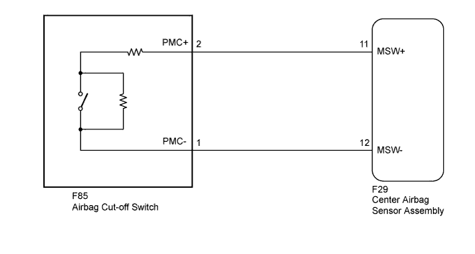
The airbag cut-off switch circuit consists of the center airbag sensor assembly and the airbag cut-off switch.
The front passenger airbag and front passenger side knee airbag can be optionally deactivated via this circuit by turning the airbag cut-off switch to the OFF position.
If the front passenger airbag and front passenger side knee airbag are deactivated, the passenger airbag ON/OFF indicator ("OFF") comes on to inform the passengers.
DTC B1651/33 is recorded when a malfunction is detected in the airbag cut-off switch circuit.
| DTC No. | DTC Detecting Condition | Trouble Area |
|---|---|---|
| B1651/33 |
|
|
WIRING DIAGRAM
INSPECTION PROCEDURE
Tech Tips
The F29-11 (MSW+) and F29-12 (MSW-) terminals in this circuit have an activation prevention mechanism.
This mechanism can be used to check for an open circuit in the wire harness. In case of other checks (check for short, short to ground or short to B+), this mechanism should be released.
PROCEDURE
-
CHECK CONNECTORS
-
Turn the power switch off.
-
Disconnect the cable from the negative (-) battery terminal.
Note
Wait at least 90 seconds after disconnecting the cable from the negative (-) battery terminal to disable the SRS system.
-
Check that the connectors are properly connected to the center airbag sensor assembly and airbag cut-off switch.
OK The connectors are properly connected. Tech Tips
If the connector is not connected securely, reconnect the connector and proceed to the next inspection.
-
Disconnect the connectors from the center airbag sensor assembly and airbag cut-off switch.
-
Check that the terminals of the connectors are not damaged.
OK The terminals are not deformed or damaged. -
Check that the short spring for the instrument panel wire connector with the activation prevention mechanism is not deformed or damaged.
OK The short spring is not deformed or damaged.
NG 
REPLACE INSTRUMENT PANEL WIRE
OK 
-
-
CHECK INSTRUMENT PANEL WIRE (OPEN)
-
Measure the resistance according to the value(s) in the table below.
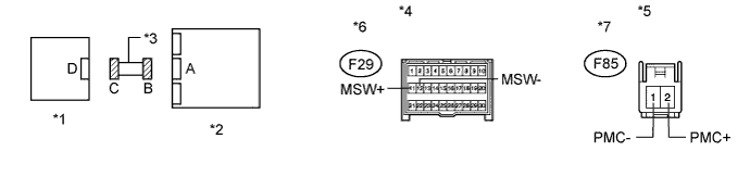
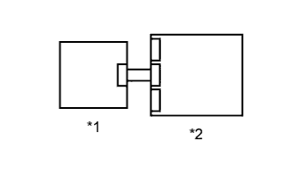
Standard Resistance Tester Connection Condition Specified Condition F85-2 (PMC+) - F85-1 (PMC-) Always Below 1 Ω Text in Illustration *1 Airbag Cut-off Switch *2 Center Airbag Sensor Assembly *3 Instrument Panel Wire *4 Front view of wire harness connector
(to Center Airbag Sensor Assembly)
*5 Front view of wire harness connector
(to Airbag Cut-off Switch)
*6 Connector B *7 Connector C - -
NG
REPLACE INSTRUMENT PANEL WIRE
OK
-
-
CHECK INSTRUMENT PANEL WIRE (SHORT)
-
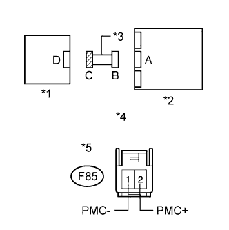
Text in Illustration *1 Airbag Cut-off Switch *2 Center Airbag Sensor Assembly *3 Instrument Panel Wire *4 Front view of wire harness connector
(to Airbag Cut-off Switch)
*5 Connector C Release the activation prevention mechanism built into connector B Click here.
-
Measure the resistance according to the value(s) in the table below.
Standard Resistance Tester Connection Condition Specified Condition F85-2 (PMC+) - F85-1 (PMC-) Always 1 MΩ or higher
NG
REPLACE INSTRUMENT PANEL WIRE
OK
-
-
CHECK INSTRUMENT PANEL WIRE (SHORT TO B+)
-
Text in Illustration *1 Airbag Cut-off Switch *2 Center Airbag Sensor Assembly *3 Instrument Panel Wire *4 Front view of wire harness connector
(to Airbag Cut-off Switch)
*5 Connector C Connect the cable to the negative (-) battery terminal.
-
Turn the power switch on (IG).
-
Measure the voltage according to the value(s) in the table below.
Standard Voltage Tester Connection Switch Condition Specified Condition F85-2 (PMC+) - Body ground Power switch on (IG) Below 1 V F85-1 (PMC-) - Body ground Power switch on (IG) Below 1 V
NG
REPLACE INSTRUMENT PANEL WIRE
OK
-
-
CHECK INSTRUMENT PANEL WIRE (SHORT TO GROUND)
-
Text in Illustration *1 Airbag Cut-off Switch *2 Center Airbag Sensor Assembly *3 Instrument Panel Wire *4 Front view of wire harness connector
(to Airbag Cut-off Switch)
*5 Connector C Turn the power switch off.
-
Disconnect the cable from the negative (-) battery terminal.
Note
Wait at least 90 seconds after disconnecting the cable from the negative (-) battery terminal to disable the SRS system.
-
Measure the resistance according to the value(s) in the table below.
Standard Resistance Tester Connection Condition Specified Condition F85-2 (PMC+) - Body ground Always 1 MΩ or higher F85-1 (PMC-) - Body ground Always 1 MΩ or higher
NG
REPLACE INSTRUMENT PANEL WIRE
OK
-
-
INSPECT AIRBAG CUT-OFF SWITCH
-
Remove the airbag cut-off switch Click here.
-
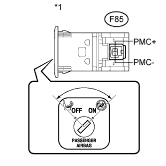
Text in Illustration *1 Component without harness connected
(Airbag Cut-off Switch)
Measure the resistance according to the value(s) in the table below.
Standard Resistance Tester Connection Switch Condition Specified Condition F85-2 (PMC+) - F85-1 (PMC-) Cut off switch is in ON position 360 to 440 Ω F85-2 (PMC+) - F85-1 (PMC-) Cut off switch is in OFF position 90 to 110 Ω
NG
REPLACE AIRBAG CUT-OFF SWITCH Click here
OK
-
-
CHECK CENTER AIRBAG SENSOR ASSEMBLY
-
Text in Illustration *1 Airbag Cut-off Switch *2 Center Airbag Sensor Assembly Restore the released activation prevention mechanism of connector B to the original condition.
-
Connect the connectors to the center airbag sensor assembly and airbag cut-off switch.
-
Connect the cable to the negative (-) battery terminal.
-
Turn the power switch on (IG), and wait for at least 60 seconds.
-
Clear the DTCs stored in the memory Click here.
-
Turn the power switch off.
-
Turn the power switch on (IG), and wait for at least 60 seconds.
-
Check for DTCs Click here.
OK DTC B1651/33 is not output. Tech Tips
Codes other than DTC B1651/33 may be output at this time, but they are not related to this check.
NG
REPLACE CENTER AIRBAG SENSOR ASSEMBLY Click here
OK 
USE SIMULATION METHOD TO CHECK Click here
-