HEADUP DISPLAY ADJUSTMENT

Note
Adjust the headup display image angle only when the user is concerned about the angle of the image.
-
CHECK HEADUP DISPLAY IMAGE ANGLE
-
Determine the headup display image angle by referring to the illustration.
Note
-
Perform the check with the image displayed at the position where the user normally keeps it, while observing it from a viewpoint similar to the user's.
-
Make sure to perform the check in a level place.
-
Make sure to use a horizontal line in front of the vehicle (do not use the instrument panel or hood) to check the image angle.
-
The angle that should be checked is not the angle between the image and vehicle. The angle that should be checked is the angle between the image and the landscape in front of the vehicle.
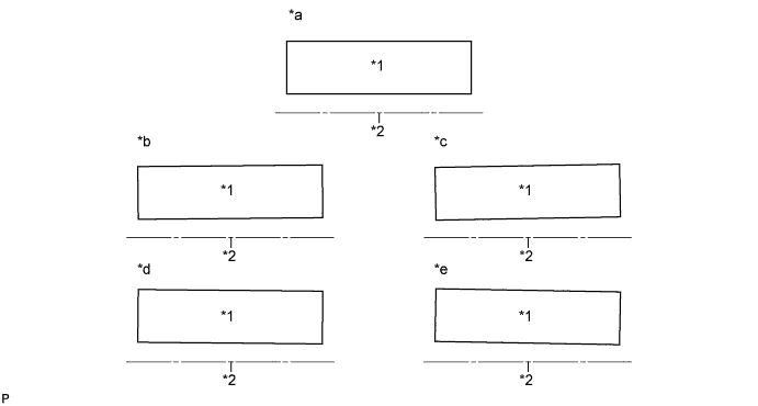
Text in Illustration *1 Image from headup display *2 Horizontal line in front of the vehicle *a Parallel to horizontal line *b 0.4° tilted to the left *c 0.8° tilted to the left *d 0.4° tilted to the right *e 0.8° tilted to the right - - -
-
-
REMOVE COMBINATION METER MIRROR ECU
-
Remove the combination meter mirror ECU Click here.
-
-
ADJUST HEADUP DISPLAY IMAGE ANGLE
Note
-
When disassembling the combination meter mirror ECU, eliminate static electricity by touching the vehicle body to prevent components from being damaged.
-
Do not touch the mirror portion or the LCD and backlight assembly. If either of these is touched, wipe them with a soft cloth.
-
Take care that no dust or foreign matter enters the headup display. If anything enters, remove it using an oil and water free air blower, etc.
-
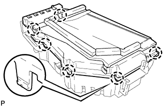
Disengage the 6 claws and remove the upper case.
-
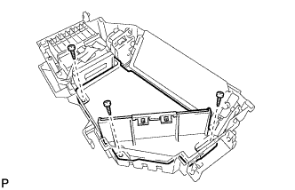
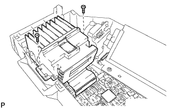
Remove the 3 screws and remove the inner case.
-
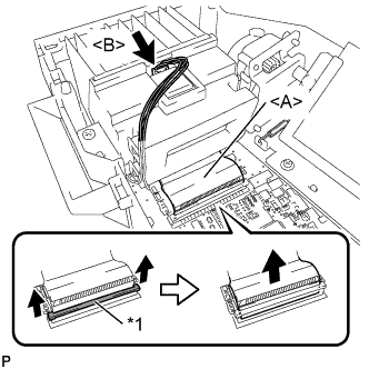
Text in Illustration *1 Retainer Pull the both sides of the retainer toward the direction indicated by the arrow shown in the illustration.
-
Disconnect the ribbon cable <A> from the connector.
-
Disconnect the connector <B>.
-
Remove the 2 screws and the LCD and backlight assembly.
-
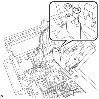
When the displayed image is tilted to the right:
-
Set the washers at the positions shown in the illustration.
Note
Use a maximum of 4 washers (2 washers for each position).
Tech Tips
-
Washer part number (90201-04006)
-
When the displayed image is tilted approximately 0.4° to the right, use 1 washer for each position. When the displayed image is tilted approximately 0.8° to the right, use 2 washers for each position.
-
-
-
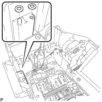
When the displayed image is tilted to the left:
-
Set the washers at the positions shown in the illustration.
Note
Use a maximum of 4 washers (2 washers for each position).
Tech Tips
-
Washer part number (90201-04006)
-
When the displayed image is tilted approximately 0.4° to the left, use 1 washer for each position. When the displayed image is tilted approximately 0.8° to the left, use 2 washers for each position.
-
-
-
Install the LCD and backlight assembly with the 2 screws.
-
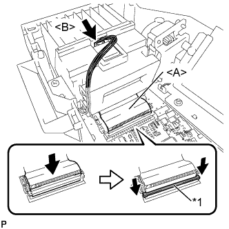
Text in Illustration *1 Retainer Connect the ribbon cable <A> to the connector.
-
Push down the both sides of the retainer as indicated by the arrow shown in the illustration.
Note
Check that the retainer is fully pushed down.
-
Connect the connector <B>.
-
Install the inner case with the 3 screws.
-
Engage the 6 claws to install the upper case.
-
-
INSTALL COMBINATION METER MIRROR ECU
-
Install the combination meter mirror ECU Click here.
-