METER / GAUGE SYSTEM Headup Display Malfunction
DESCRIPTION
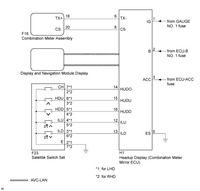
This circuit is the power source circuit for the headup display (combination meter mirror ECU). This circuit provides two types of power sources; one is a constant power source mainly used as a backup power source, and the other is a power source mainly used for signal transmission.
WIRING DIAGRAM
INSPECTION PROCEDURE
Tech Tips
Before starting the following inspection, confirm the headup display (combination meter mirror ECU) position illuminance, then perform the on-vehicle inspection Click here.
PROCEDURE
-
SYSTEM CHECK
-
Check the symptom of the headup display (combination meter mirror ECU).
Result Result Proceed to Headup display (combination meter mirror ECU) does not operate at all. A Cruise information display does not change. B
B 
SYSTEM CHECK Click here
A 
-
-
CHECK HARNESS AND CONNECTOR (HEADUP DISPLAY CIRCUIT)
-
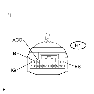
Text in Illustration *1 Front view of wire harness connector
(to Headup Display (Combination Meter Mirror ECU))
Disconnect the H1 connector.
-
Measure the voltage according to the value(s) in the table below.
Standard Voltage Tester Connection Condition Specified Condition H1-1 (IG) - Body ground Power switch on (IG) 11 to 14 V H1-2 (B) - Body ground Power switch off 11 to 14 V H1-3 (ACC) - Body ground Power switch on (ACC) 11 to 14 V -
Measure the resistance according to the value(s) in the table below
Standard Resistance Tester Connection Condition Specified Condition H1-5 (ES) - Body ground Always Below 1 Ω
NG 
REPAIR OR REPLACE HARNESS OR CONNECTOR
OK
-
-
CHECK HARNESS AND CONNECTOR (HEADUP DISPLAY - SATELLITE SWITCH SET)
-
for LHD
-
Disconnect the H1 and F23 connectors.
-
Measure the resistance according to the value(s) in the table below.
Standard Resistance Tester Connection Condition Specified Condition H1-14 (HUDO) - F23-7 (CH) Always Below 1 Ω H1-14 (HUDO) - Body ground Always 10 kΩ or higher H1-15 (HUDU) - F23-6 (HDU) Always Below 1 Ω H1-15 (HUDU) - Body ground Always 10 kΩ or higher H1-16 (HUDD) - F23-5 (HDD) Always Below 1 Ω H1-16 (HUDD) - Body ground Always 10 kΩ or higher H1-12 (ILU) - F23-4 (ILU) Always Below 1 Ω H1-12 (ILU) - Body ground Always 10 kΩ or higher H1-13 (ILD) - F23-3 (ILD) Always Below 1 Ω H1-13 (ILD) - Body ground Always 10 kΩ or higher
-
-
for RHD
-
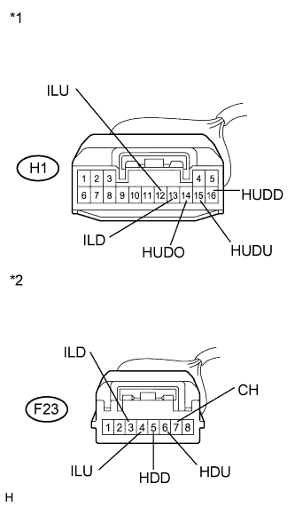
Text in Illustration *1 Front view of wire harness connector
(to Headup Display (Combination Meter Mirror ECU))
*2 Front view of wire harness connector
(to Satellite Switch Set)
Disconnect the H1 and F23 connectors.
-
Measure the resistance according to the value(s) in the table below.
Standard Resistance Tester Connection Condition Specified Condition H1-14 (HUDO) - F23-2 (CH) Always Below 1 Ω H1-14 (HUDO) - Body ground Always 10 kΩ or higher H1-15 (HUDU) - F23-3 (HDU) Always Below 1 Ω H1-15 (HUDU) - Body ground Always 10 kΩ or higher H1-16 (HUDD) - F23-4 (HDD) Always Below 1 Ω H1-16 (HUDD) - Body ground Always 10 kΩ or higher H1-12 (ILU) - F23-5 (ILU) Always Below 1 Ω H1-12 (ILU) - Body ground Always 10 kΩ or higher H1-13 (ILD) - F23-6 (ILD) Always Below 1 Ω H1-13 (ILD) - Body ground Always 10 kΩ or higher
-
NG
REPAIR OR REPLACE HARNESS OR CONNECTOR
OK
-
-
INSPECT SATELLITE SWITCH SET
-
for LHD
-
Disconnect the H1 connector.
-
Measure the resistance according to the value(s) in the table below.
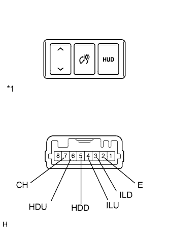
Standard Resistance Tester Connection Switch Condition Specified Condition 2 (E) - 3 (ILD) Display contrast down switch pressed Below 1 Ω 2 (E) - 3 (ILD) Display contrast down switch not pressed 10 kΩ or higher 2 (E) - 4 (ILU) Display contrast up switch pressed Below 1 Ω 2 (E) - 4 (ILU) Display contrast up switch not pressed 10 kΩ or higher 2 (E) - 5 (HDD) Headup display (combination meter mirror ECU) position down switch pressed Below 1 Ω 2 (E) - 5 (HDD) Headup display (combination meter mirror ECU) position down switch not pressed 10 kΩ or higher 2 (E) - 6 (HDU) Headup display (combination meter mirror ECU) position up switch pressed Below 1 Ω 2 (E) - 6 (HDU) Headup display (combination meter mirror ECU) position up switch not pressed 10 kΩ or higher 2 (E) - 7 (CH) Headup display (combination meter mirror ECU) on switch pressed Below 1 Ω 2 (E) - 7 (CH) Headup display (combination meter mirror ECU) on switch not pressed 10 kΩ or higher
-
-
for RHD
-
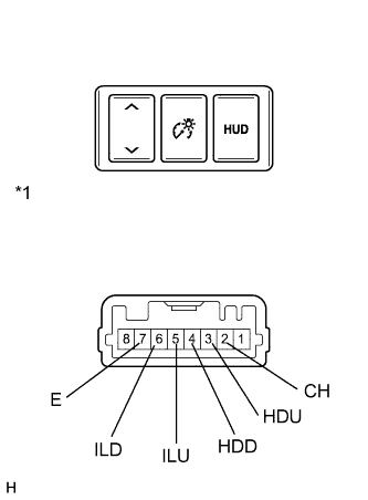
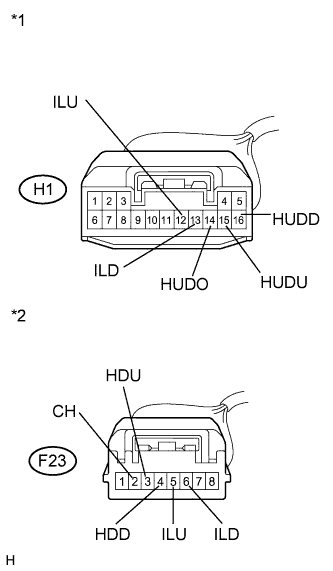
Text in Illustration *1 Component without harness connected
(Satellite Switch Set)
Disconnect the H1 connector.
-
Measure the resistance according to the value(s) in the table below.
Standard Resistance Tester Connection Switch Condition Specified Condition 6 (ILD) - 7 (E) Display contrast down switch pressed Below 1 Ω 6 (ILD) - 7 (E) Display contrast down switch not pressed 10 kΩ or higher 5 (ILU) - 7 (E) Display contrast up switch pressed Below 1 Ω 5 (ILU) - 7 (E) Display contrast up switch not pressed 10 kΩ or higher 4 (HDD) - 7 (E) Headup display (combination meter mirror ECU) position down switch pressed Below 1 Ω 4 (HDD) - 7 (E) Headup display (combination meter mirror ECU) position down switch not pressed 10 kΩ or higher 3 (HDU) - 7 (E) Headup display (combination meter mirror ECU) position up switch pressed Below 1 Ω 3 (HDU) - 7 (E) Headup display (combination meter mirror ECU) position up switch not pressed 10 kΩ or higher 2 (CH) - 7 (E) Headup display (combination meter mirror ECU) on switch pressed Below 1 Ω 2 (CH) - 7 (E) Headup display (combination meter mirror ECU) on switch not pressed 10 kΩ or higher
-
NG
REPLACE SATELLITE SWITCH SET Click here
OK 
REPLACE HEADUP DISPLAY (COMBINATION METER MIRROR ECU) Click here
-
-
SYSTEM CHECK
-
Confirm the symptoms.
Result Result Proceed to All the display malfunction A Vehicle speed display malfunction Dynamic radar cruise control display malfunction Pre-crash safety system display malfunction Navigation display malfunction B
B
CONFIRM DTC OUTPUT Click here
A
-
-
CONFIRM DTC OUTPUT
-
Check for DTCs Click here.
Result Result Proceed to DTC is output. A DTC is not output. B
B
REPLACE HEADUP DISPLAY (COMBINATION METER MIRROR ECU) Click here
A
-
-
CHECK HARNESS AND CONNECTOR (COMBINATION METER ASSEMBLY - HEADUP DISPLAY)
-
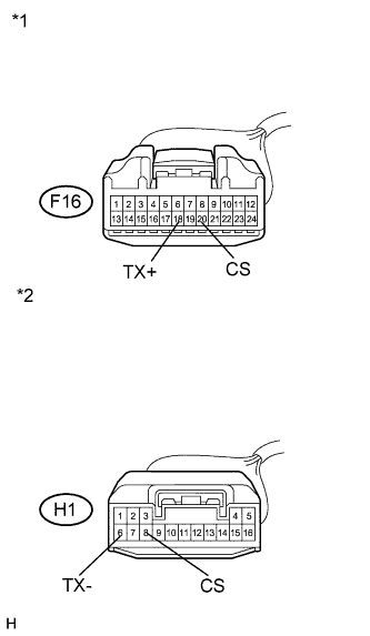
Text in Illustration *1 Front view of wire harness connector
(to Combination Meter Assembly)
*2 Front view of wire harness connector
(to Headup Display (Combination Meter Mirror ECU))
Disconnect the F16 and H1 connectors.
-
Measure the resistance according to the value(s) in the table below.
Standard Resistance Tester Connection Condition Specified Condition F16-18 (TX+) - H1-6 (TX-) Always Below 1 Ω F16-18 (TX+) - Body ground Always 10 kΩ or higher F16-20 (CS) - H1-8 (CS) Always Below 1 Ω F16-20 (CS) - Body ground Always 10 kΩ or higher
NG
REPAIR OR REPLACE HARNESS OR CONNECTOR
OK
-
-
REPLACE HEADUP DISPLAY (COMBINATION METER MIRROR ECU)
-
Replace the headup display (combination meter mirror ECU) with a new or a known good one. Click here.
OK The operation of the headup display (combination meter mirror ECU) returns to normal.
NG
REPLACE COMBINATION METER ASSEMBLY Click here
OK
END
-
-
CONFIRM DTC OUTPUT
-
Check for DTCs Click here.
Result Result Proceed to DTC is output. A DTC is not output. B
B
REPLACE COMBINATION METER ASSEMBLY Click here
A
-
-
CHECK HARNESS AND CONNECTOR (COMBINATION METER ASSEMBLY - HEADUP DISPLAY)
-
Text in Illustration *1 Front view of wire harness connector
(to Combination Meter Assembly)
*2 Front view of wire harness connector
(to Headup Display (Combination Meter Mirror ECU))
Disconnect the F16 and H1 connectors.
-
Measure the resistance according to the value(s) in the table below.
Standard Resistance Tester Connection Condition Specified Condition F16-18 (TX+) - H1-6 (TX-) Always Below 1 Ω F16-18 (TX+) - Body ground Always 10 kΩ or higher F16-20 (CS) - H1-8 (CS) Always Below 1 Ω F16-20 (CS) - Body ground Always 10 kΩ or higher
NG
REPAIR OR REPLACE HARNESS OR CONNECTOR
OK
-
-
REPLACE COMBINATION METER ASSEMBLY
-
Replace the combination meter assembly to a new or a normal one Click here.
Result The operation of the headup display (combination meter mirror ECU) returns to normal.
NG
REPLACE HEADUP DISPLAY Click here
OK
END
-
-
REPLACE HEADUP DISPLAY
-
Replace the headup display (combination meter mirror ECU) to a new or a normal one Click here.
Result The operation of the headup display (combination meter mirror ECU) returns to normal.
NG
REPLACE RADIO RECEIVER ASSEMBLY
OK
END
-