METER / GAUGE SYSTEM Accessory Meter does not Illuminate
DESCRIPTION
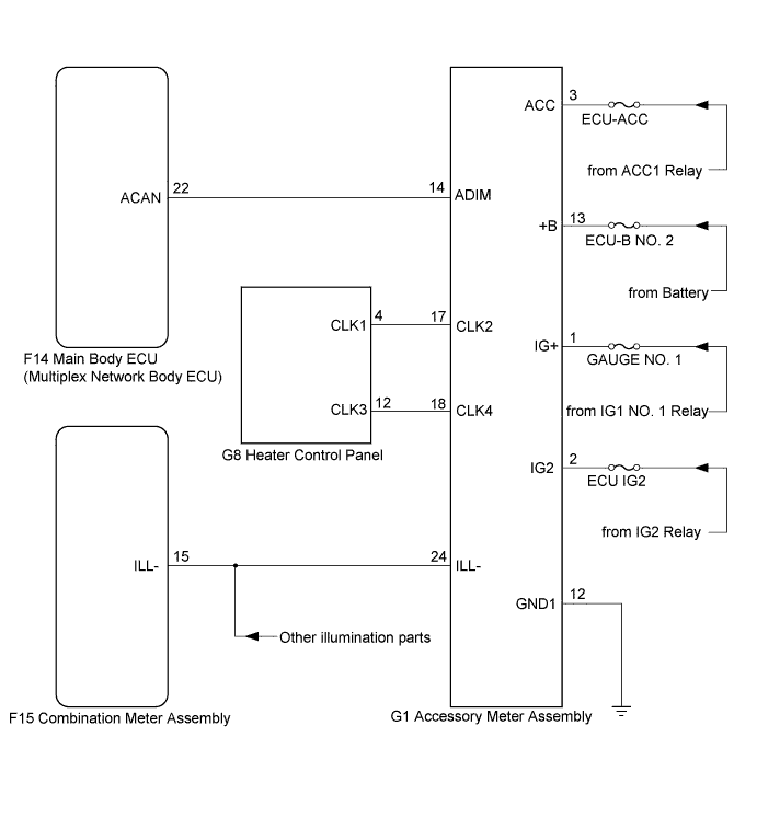
This circuit provides power to the accessory meter assembly.
The clock and accessory meter illuminance can be adjusted by pressing the H, M, or light adjustment switch in the heater control panel.
Tech Tips
-
The whole heater control panel should be replaced if any of the switches is malfunctioning.
-
If the accessory meter assembly displays "1:00" in turning the power switch off, then to on (IG) again, the +B terminal has a malfunction.
-
The maximum clock assembly margin of error is -4 to 4 seconds per day when the temperature is between -20°C (-4°F) and 60°C (140°F).
WIRING DIAGRAM
INSPECTION PROCEDURE
PROCEDURE
-
CHECK ACCESSORY METER ASSEMBLY
-
Check type of accessory meter assembly malfunction.
Result Result Proceed to Accessory meter assembly does not display at all. A Accessory meter assembly does not dim at night. B Clock cannot be adjusted. C
B 
SYSTEM CHECK Click here
C
CHECK HARNESS AND CONNECTOR (HEATER CONTROL PANEL - ACCESSORY METER ASSEMBLY) Click here
A 
-
-
INSPECT FUSE (ECU-ACC, ECU-B NO. 1, ECU-B NO. 2, ECU-IG2)
-
Measure the resistance according to the value(s) in the table below.
Standard Resistance Tester Connection Condition Specified Condition ECU-ACC fuse Always Below 1 Ω ECU-B No. 1 fuse Always Below 1 Ω ECU-B No. 2 fuse Always Below 1 Ω ECU-IG2 fuse Always Below 1 Ω
NG 
REPLACE FUSE
OK
-
-
CHECK HARNESS AND CONNECTOR (ACCESSORY METER ASSEMBLY CIRCUIT)
-
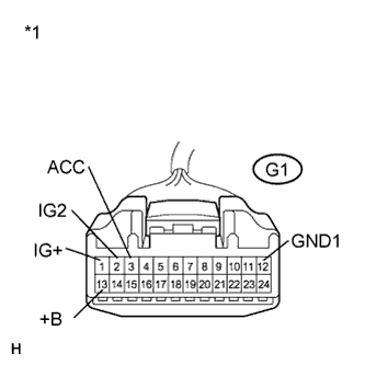
Text in Illustration *1 Front view of wire harness connector
(to Accessory Meter Assembly)
Disconnect the G1 connector.
-
Measure the voltage according to the value(s) in the table below.
Standard Voltage Tester Connection Condition Specified Condition G1-1 (IG+) - Body ground Power switch on (IG) 11 to 14 V G1-2 (IG2) - Body ground Power switch on (IG) 11 to 14 V G1-3 (ACC) - Body ground power switch on (ACC) 11 to 14 V G1-13 (+B) - Body ground Power switch off 11 to 14 V -
Measure the resistance according to the value(s) in the table below.
Standard Resistance Tester Connection Condition Specified Condition G1-12 (GND1) - Body ground Always Below 1 Ω
NG
REPAIR OR REPLACE HARNESS OR CONNECTOR
OK 
REPLACE ACCESSORY METER ASSEMBLY Click here
-
-
SYSTEM CHECK
-
Confirm the symptoms.
Result Result Proceed to All illumination parts does not dim at night. A Only accessory meter assembly illumination does not dim at night. B
B
INSPECT MULTIPLEX NETWORK BODY ECU Click here
A
REPLACE COMBINATION METER ASSEMBLY Click here
-
-
INSPECT MULTIPLEX NETWORK BODY ECU
-
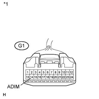
Text in Illustration *1 Front view of wire harness connector
(to Accessory Meter Assembly)
Disconnect the G1 connector.
-
Measure the voltage according to the value(s) in the table below.
Standard Voltage Tester Connection Condition Specified Condition G1-14 (ADIM) - Body ground Power switch on (IG), turn the light control switch to the tail or head position. 4 V or more
NG
CHECK HARNESS AND CONNECTOR (ACCESSORY METER ASSEMBLY - MAIN BODY ECU) Click here
OK
-
-
CHECK HARNESS AND CONNECTOR (ACCESSORY METER ASSEMBLY - COMBINATION METER ASSEMBLY)
-
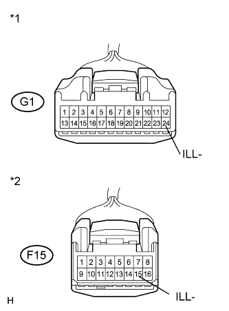
Text in Illustration *1 Front view of wire harness connector
(to Accessory Meter Assembly)
*2 Front view of wire harness connector
(to Combination Meter Assembly)
Disconnect the F15 connector.
-
Disconnect the G1 connector.
-
Measure the resistance according to the value(s) in the table below.
Standard Resistance Tester Connection Condition Specified Condition G1-24 (ILL-) - F15-15 (ILL-) Always Below 1 Ω G1-24 (ILL-) - Body ground Always 10 kΩ or higher
NG
REPAIR OR REPLACE HARNESS OR CONNECTOR
OK
REPLACE ACCESSORY METER ASSEMBLY Click here
-
-
CHECK HARNESS AND CONNECTOR (ACCESSORY METER ASSEMBLY - MAIN BODY ECU)
-
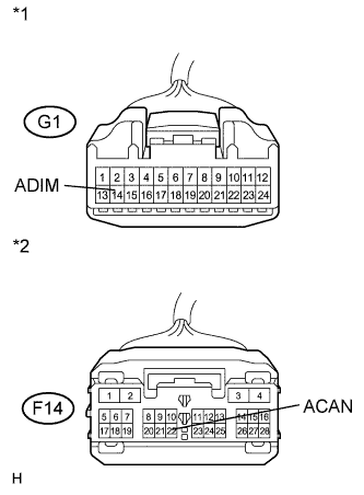
Text in Illustration *1 Front view of wire harness connector
(to Accessory Meter Assembly)
*2 Front view of wire harness connector
(to Main Body ECU (Multiplex Network Body ECU))
Disconnect the F14 connector.
-
Disconnect the G1 connector.
-
Measure the resistance according to the value(s) in the table below.
Standard Resistance Tester Connection Condition Specified Condition G1-14 (ADIM) - F14-22 (ACAN) Always Below 1 Ω G1-14 (ADIM) - Body ground Always 10 kΩ or higher
NG
REPAIR OR REPLACE HARNESS OR CONNECTOR
OK
REPLACE ACCESSORY METER ASSEMBLY Click here
-
-
CHECK HARNESS AND CONNECTOR (HEATER CONTROL PANEL - ACCESSORY METER ASSEMBLY)
-
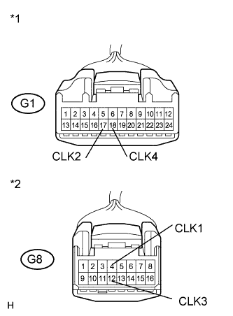
Text in Illustration *1 Front view of wire harness connector
(to Accessory Meter Assembly)
*2 Front view of wire harness connector
(to Heater Control Panel)
Disconnect the G8 connector.
-
Disconnect the G1 connector.
-
Measure the resistance according to the value(s) in the table below.
Standard Resistance Tester Connection Condition Specified Condition G1-17 (CLK2) - G8-4 (CLK1) Always Below 1 Ω G1-17 (CLK2) - Body ground Always 10 kΩ or higher G1-18 (CLK4) - G8-12 (CLK3) Always Below 1 Ω G1-18 (CLK4) - Body ground Always 10 kΩ or higher
NG
REPAIR OR REPLACE HARNESS OR CONNECTOR
OK
-
-
INSPECT HEATER CONTROL PANEL
-
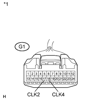
Text in Illustration *1 Front view of wire harness connector
(to Accessory Meter Assembly)
Remove the heater control panel Click here.
-
Measure the resistance according to the value(s) in the table below.
Standard Resistance Tester Connection Switch Condition Specified Condition G1-17 (CLK2) - G1-18 (CLK4) H switch pressed Below 1 Ω H switch not pressed 10 kΩ or higher G1-17 (CLK2) - G1-18 (CLK4) M switch pressed Below 1 Ω M switch not pressed 10 kΩ or higher G1-17 (CLK2) - G1-18 (CLK4) : switch pressed Below 1 Ω : switch not pressed 10 kΩ or higher
NG
REPLACE HEATER CONTROL PANEL Click here
OK
REPLACE ACCESSORY METER ASSEMBLY Click here
-