METER / GAUGE SYSTEM Meter Illumination does not Dim at Night
DESCRIPTION
In this circuit, the meter CPU receives auto dimmer signals from the main body ECU (multiplex network body ECU) using the CAN communication system (CAN No. 1 Bus). When the meter CPU receives an auto dimmer signal, it dims the meter illumination (warning and indicator lights). The main body ECU (multiplex network body ECU) determines whether it is daytime, twilight, or nighttime based on the waveform transmitted from the automatic light control sensor. If the main body ECU (multiplex network body ECU) determines that it is nighttime and the light control switch is in the tail, head, or AUTO position, the ECU sends an auto dimmer signal. According to the signal, the combination meter assembly dims the meter illumination.
Tech Tips
When the meter illumination does not dim at night, there may be a malfunction in the automatic light control sensor, main body ECU (multiplex network body ECU), CAN communication system, harness or connector, or combination meter assembly.
WIRING DIAGRAM
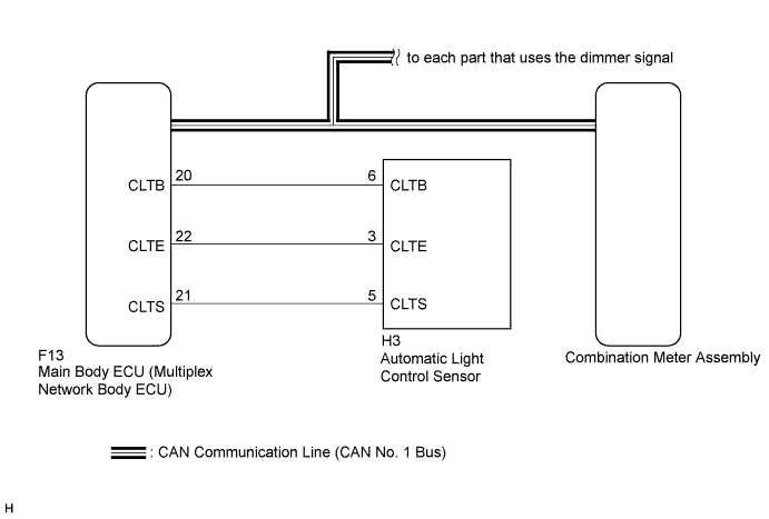
INSPECTION PROCEDURE
Tech Tips
-
The automatic light control sensor sensitiveness can be customized Click here.
-
Setting the meter illumination to maximum brightness prevents the meter illumination from dimming when the light control switch is changed to the tail or head position, or changed to the AUTO position at night. Therefore, check the meter illumination setting before proceeding to the following steps.
PROCEDURE
-
CHECK CAN COMMUNICATION SYSTEM
-
Check if a CAN communication DTC is output Click here.
Result Result Proceed to CAN communication DTC is not output. A CAN communication DTC is output. B
B 
GO TO CAN COMMUNICATION SYSTEM Click here
A 
-
-
CHECK DTC (LIGHT CONTROL SENSOR CIRCUIT)
-
Check if DTC B1244 is output Click here.
Result Result Proceed to B1244 is not output. A B1244 is output. B
B
GO TO LIGHTING SYSTEM Click here
A
-
-
CHECK OPERATION (HEATER CONTROL PANEL)
-
Turn the power switch on (IG).
-
Turn the light control switch to the tail, head, or AUTO position.
-
Cover the light control switch.
-
Check the heater control panel illumination.
Result Result Proceed to Heater control panel illumination does not operate normally. A Heater control panel illumination operates normally. B Tech Tips
Both the heater control panel and combination meter assembly illumination dim according to the dimmer signal. Therefore, when only the meter illumination does not dim at night, replace the combination meter assembly.
B
REPLACE COMBINATION METER ASSEMBLY Click here
A
-
-
CHECK OPERATION (AUTOMATIC LIGHT CONTROL SYSTEM)
-
Turn the power switch on (IG).
-
Turn the light control switch to the AUTO position.
-
Cover the automatic light control sensor.
-
Check that the taillights and low beam headlights.
OK The taillights and low beam headlights come on. -
Uncover the automatic light control sensor.
-
Check that the low beam headlights and taillights.
OK The low beam headlights and taillights go off. Result Result Proceed to Automatic light control system operates normally. A Automatic light control system does not operate normally. B
B
CHECK LIGHTING SETTING Click here
A
-
-
REPLACE MULTIPLEX NETWORK BODY ECU
-
Replace the main body ECU (multiplex network body ECU) with a new or a known good one Click here.
OK The operation of the combination meter assembly returns to normal. Tech Tips
The meter CPU controls the meter illumination based on an auto dimmer signal from the main body ECU (multiplex network body ECU). If the meter does not dim when the light control switch is in the tail, head, or AUTO position at night, it may be for either of 2 reasons. The first reason is that the main body ECU (multiplex network body ECU) does not send an auto dimmer signal. The second is that the meter CPU does not dim the meter illumination even though the meter CPU receives an auto dimmer signal.
NG
REPLACE COMBINATION METER ASSEMBLY Click here
OK 
END
-