METER / GAUGE SYSTEM Engine Coolant Temperature Receiver Gauge Malfunction
DESCRIPTION
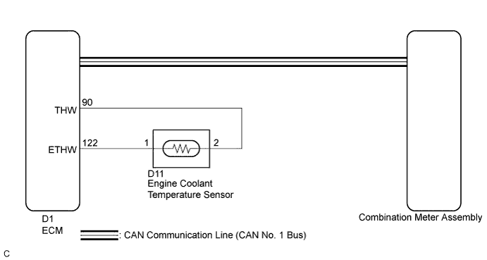
In this circuit, the meter CPU receives engine coolant temperature signals from the ECM using the CAN communication system (CAN No. 1 Bus). The meter CPU displays engine coolant temperature that is calculated based on the data received from the ECM.
In addition to above, this model of vehicle is equipped with the exhaust heat recirculation system. Therefore, the combination meter assembly also receives the engine coolant temperature signals from the coolant temperature sensor via the direct line too.
WIRING DIAGRAM
INSPECTION PROCEDURE
Tech Tips
-
If there is an open or short in the engine coolant temperature sensor circuit, the ECM stores the DTCs. Troubleshoot the SFI System Click here for 2GR-FXE).
-
If the exhaust heat recirculation system has a malfunction, the engine coolant temperature receiver gauge indicate the maximum reading to inform the driver of the malfunction Click here for 2GR-FXE).
PROCEDURE
-
CHECK CAN COMMUNICATION SYSTEM
-
Check if a CAN communication DTC is output Click here.
Result Result Proceed to CAN communication DTC is not output. A CAN communication DTC is output. B
B 
GO TO CAN COMMUNICATION SYSTEM Click here
A 
-
-
PERFORM ACTIVE TEST USING INTELLIGENT TESTER (WATER TEMPERATURE METER OPERATION)
-
Connect the intelligent tester to the DLC3.
-
Turn the power switch on (IG).
-
Turn the tester on.
-
Enter the following menus: Body Electrical / Combination Meter / Active Test.
-
Check the operation by referring to the table below.
Combination Meter Tester Display Test Part Control Range Diagnostic Note Water Temperature Meter Operation Engine coolant temperature receiver gauge Low, Normal, Hi Confirm that the vehicle is stopped with the engine idling OK Engine coolant temperature receiver gauge indication is normal.
NG
REPLACE COMBINATION METER ASSEMBLY Click here
OK
-
-
READ VALUE USING INTELLIGENT TESTER (COOLANT TEMPERATURE)
-
Connect the intelligent tester to the DLC3.
-
Turn the power switch on (IG).
-
Turn the tester on.
-
Enter the following menus: Body Electrical / Combination Meter / Data List.
-
Check the values by referring to the table below.
Combination Meter Tester Display Measurement Item/Range Normal Condition Diagnostic Note Coolant Temperature Engine coolant temperature/-40 to 140°C (-40 to 284°F) After warming up: 80 to 95°C (176 to 203°F)
-
If -40°C (-40°F): Sensor circuit open
-
If 140°C (284°F) or more: Sensor circuit shorted
OK Engine coolant temperature value displayed on the intelligent tester is almost the same as the engine coolant temperature receiver gauge indication. -
-
Record the temperature displayed on the intelligent tester.
NG
REPLACE COMBINATION METER ASSEMBLY Click here
OK
-
-
READ VALUE USING INTELLIGENT TESTER (COOLANT TEMP)
-
Connect the intelligent tester to the DLC3.
-
Turn the power switch on (IG).
-
Turn the tester on.
-
Enter the following menus: Powertrain / Engine and ECT / Data List.
-
Check the values by referring to the table below.
Engine and ECT Tester Display Measurement Item/Range Normal Condition Diagnostic Note Coolant Temp Engine coolant temperature/Min.: -40°C (-40°F), Max.: 215°C (419°F) After warming up: 80 to 100°C (176 to 212°F) - OK Engine coolant temperature value displayed on the intelligent tester is almost the same as the previously recorded intelligent tester indication (Body Electrical / Combination Meter / Data List / Coolant Temperature).
NG
REPLACE ECM (for 2GR-FXE) Click here
OK 
REPLACE COMBINATION METER ASSEMBLY Click here
-