METER / GAUGE SYSTEM Operating Light Control Rheostat does not Change Light Brightness
DESCRIPTION
The meter CPU receives signals from this circuit to adjust the illumination of the meter, instrument panel, accessory meter assembly and headup display (combination meter mirror ECU). The meter CPU sets the illumination level based on the user operation of the light control rheostat up or down switches.
Tech Tips
-
The meter illumination level can be adjusted by pressing the light control rheostat up or down switches.
-
The meter illumination dims when the light control switch is turned to the tail or head position at night.
-
Setting the meter illumination to maximum brightness cancels the above dimming of the meter illumination.
-
The whole light control rheostat should be replaced if the ODO/TRIP switch is malfunctioning.
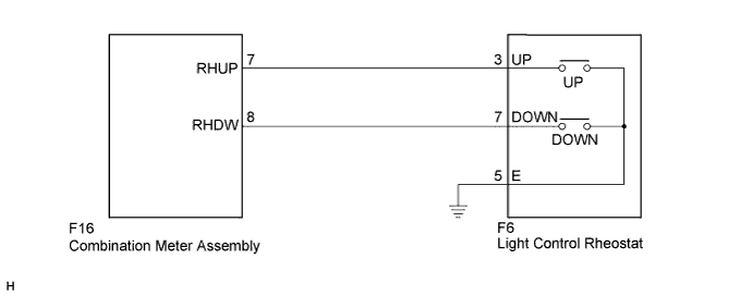
WIRING DIAGRAM
INSPECTION PROCEDURE
PROCEDURE
-
SYSTEM CHECK
-
Confirm the symptoms.
Result Result Proceed to Meter illumination does not change when operating the light control switch A Dimmer function cannot be canceled B
B 
INSPECT LIGHT CONTROL RHEOSTAT Click here
A 
-
-
READ VALUE USING INTELLIGENT TESTER (LIGHT CONTROL UP SW, LIGHT CONTROL DOWN SW)
-
Connect the intelligent tester to the DLC3.
-
Turn the power switch on (IG).
-
Turn the tester on.
-
Enter the following menus: Body Electrical / Combination Meter / Data List.
-
Check the values by referring to the table below.
Combination Meter Tester Display Measurement Item/Range Normal Condition Diagnostic Note Light Control Up SW Light control rheostat up switch/OFF or ON OFF: Light control rheostat up switch not pressed - ON: Light control rheostat up switch pressed Light Control Down SW Light control rheostat down switch/ OFF or ON OFF: Light control rheostat down switch not pressed - ON: Light control rheostat down switch pressed OK The value displayed on the intelligent tester changes with the actual rheostat switch operation.
NG
INSPECT LIGHT CONTROL RHEOSTAT Click here
OK 
REPLACE COMBINATION METER ASSEMBLY Click here
-
-
INSPECT LIGHT CONTROL RHEOSTAT
-
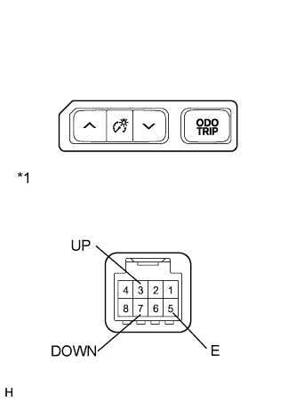
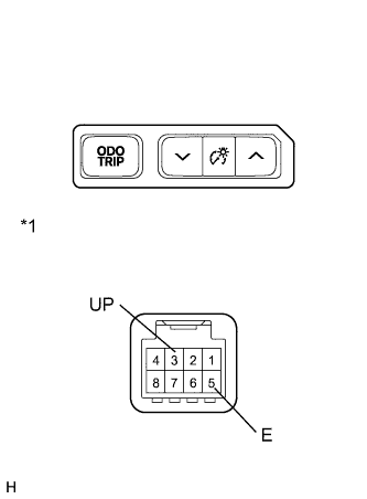
for RHD
-
Remove the light control rheostat.
-
Measure the resistance according to the value(s) in the table below.
Standard Resistance Tester Connection Switch Condition Specified Condition 3 (UP) - 5 (E) Light control rheostat up switch pressed Below 1 Ω Light control rheostat up switch not pressed 10 kΩ or higher 7 (DOWN) - 5 (E) Light control rheostat down switch pressed Below 1 Ω Light control rheostat down switch not pressed 10 kΩ or higher
-
-
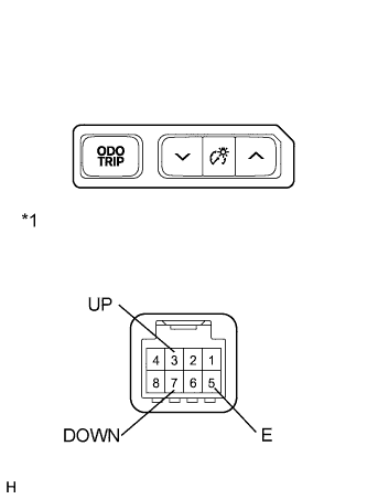
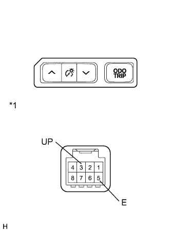
for LHD
-
Text in Illustration *1 Component without harness connected
(Light Control Rheostat)
Remove the light control rheostat.
-
Measure the resistance according to the value(s) in the table below.
Standard Resistance Tester Connection Switch Condition Specified Condition 3 (UP) - 5 (E) Light control rheostat up switch pressed Below 1 Ω Light control rheostat up switch not pressed 10 kΩ or higher 7 (DOWN) - 5 (E) Light control rheostat down switch pressed Below 1 Ω Light control rheostat down switch not pressed 10 kΩ or higher
-
NG 
REPLACE LIGHT CONTROL RHEOSTAT Click here
OK
-
-
CHECK HARNESS AND CONNECTOR (COMBINATION METER ASSEMBLY - LIGHT CONTROL RHEOSTAT)
-
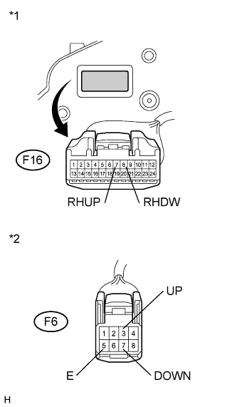
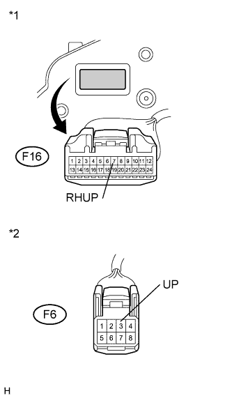
Text in Illustration *1 Front view of wire harness connector
(to Combination Meter Assembly)
*2 Front view of wire harness connector
(to Light Control Rheostat)
Disconnect the F16 and F6 connectors.
-
Measure the resistance according to the value(s) in the table below.
Standard Resistance Tester Connection Condition Specified Condition F16-7 (RHUP) - F6-3 (UP) Always Below 1 Ω F16-7 (RHUP) - Body ground Always 10 kΩ or higher F16-8 (RHDW) - F6-7 (DOWN) Always Below 1 Ω F16-8 (RHDW) - Body ground Always 10 kΩ or higher F6-5 (E) - Body ground Always Below 1 Ω
NG
REPAIR OR REPLACE HARNESS OR CONNECTOR
OK
REPLACE COMBINATION METER ASSEMBLY Click here
-
-
INSPECT LIGHT CONTROL RHEOSTAT
-
for RHD
-
Remove the light control rheostat.
-
Measure the resistance according to the value(s) in the table below.
Standard Resistance Tester Connection Switch Condition Specified Condition 3 (UP) - 5 (E) Light control up switch pressed Below 1 Ω Light control up switch not pressed 10 kΩ or higher
-
-
for LHD
-
Text in Illustration *1 Component without harness connected
(Light Control Rheostat)
Remove the light control rheostat.
-
Measure the resistance according to the value(s) in the table below.
Standard Resistance Tester Connection Switch Condition Specified Condition 3 (UP) - 5 (E) Light control up switch pressed Below 1 Ω Light control up switch not pressed 10 kΩ or higher
-
NG
REPLACE LIGHT CONTROL RHEOSTAT Click here
OK
-
-
CHECK HARNESS AND CONNECTOR (COMBINATION METER - LIGHT CONTROL RHEOSTAT)
-
Text in Illustration *1 Front view of wire harness connector
(to Combination Meter Assembly)
*2 Front view of wire harness connector
(to Light Control Rheostat)
Disconnect the F16 and F6 connectors.
-
Measure the resistance according to the value(s) in the table below.
Standard Resistance Tester Connection Condition Specified Condition F16-7 (RHUP) - F6-3 (UP) Always Below 1 Ω F16-7 (RHUP) - Body ground Always 10 kΩ or higher
NG
REPAIR OR REPLACE HARNESS OR CONNECTOR
OK
REPLACE COMBINATION METER ASSEMBLY Click here
-