METER / GAUGE SYSTEM Odo/Trip Switch Malfunction
DESCRIPTION
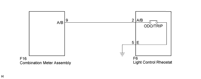
The meter CPU receives ODO/TRIP change switch signal from the light control rheostat via the direct line.
Tech Tips
The whole light control rheostat should be replaced if the ODO/TRIP switch is malfunctioning.
WIRING DIAGRAM
INSPECTION PROCEDURE
PROCEDURE
-
READ VALUE USING INTELLIGENT TESTER (ODO/TRIP CHANGE SW)
-
Connect the intelligent tester to the DLC3.
-
Turn the power switch on (IG).
-
Turn the tester on.
-
Enter the following menus: Body Electrical / Combination Meter / Data List.
-
Check the values by referring to the table below.
Combination Meter Tester Display Measurement Item/Range Normal Condition Diagnostic Note ODO/TRIP Change SW ODO/TRIP change switch/OFF or ON OFF: ODO/TRIP change switch released - ON: ODO/TRIP change switch pressed OK The value displayed on the intelligent tester changes with the actual ODO/TRIP change switch operation.
NG 
INSPECT LIGHT CONTROL RHEOSTAT Click here
OK 
REPLACE COMBINATION METER ASSEMBLY Click here
-
-
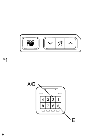
INSPECT LIGHT CONTROL RHEOSTAT
-
for RHD
-
Remove the light control rheostat.
-
Measure the resistance according to the value(s) in the table below.
Standard Resistance Tester Connection Switch Condition Specified Condition 2 (A/B) - 5 (E) ODO/TRIP change switch pressed Below 1 Ω 2 (A/B) - 5 (E) ODO/TRIP change switch not pressed 10 kΩ or higher
-
-
for LHD
-
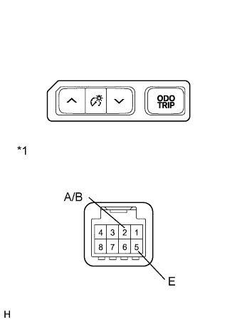
Text in Illustration *1 Component without harness connected
(Light Control Rheostat)
Remove the light control rheostat.
-
Measure the resistance according to the value(s) in the table below.
Standard Resistance Tester Connection Switch Condition Specified Condition 2 (A/B) - 5 (E) ODO/TRIP change switch pressed Below 1 Ω 2 (A/B) - 5 (E) ODO/TRIP change switch not pressed 10 kΩ or higher
-
NG 
REPLACE LIGHT CONTROL RHEOSTAT Click here
OK 
-
-
CHECK HARNESS AND CONNECTOR (COMBINATION METER ASSEMBLY - LIGHT CONTROL RHEOSTAT)
-
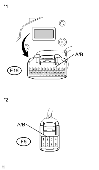
Text in Illustration *1 Front view of wire harness connector
(to Combination Meter Assembly)
*2 Front view of wire harness connector
(to Light Control Rheostat)
Disconnect the F16 connector.
-
Measure the resistance according to the value(s) in the table below.
Standard Resistance Tester Connection Condition Specified Condition F16-9 (A/B) - F6-2 (A/B) Always Below 1 Ω F16-9 (A/B) - Body ground Always 10 kΩ or higher
NG
REPAIR OR REPLACE HARNESS OR CONNECTOR
OK
REPLACE COMBINATION METER ASSEMBLY Click here
-