PERSONAL LIGHT INSPECTION

-
INSPECT MAP LIGHT ASSEMBLY
-
Inspect the interior lights.
-
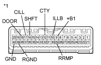
Text in Illustration *1 Component without harness connected
(Map Light Assembly)
Connect a positive (+) lead from the battery to terminal 9 (+B1) and a negative (-) lead to terminal 12 (CTY).
-
Check that the interior lights come on.
OK Interior lights come on. If the result is not as specified, replace the map light assembly.
-
-
Inspect the interior light door switch and on/off switch.
-
Measure the resistance according to the value(s) in the table below.
Standard Resistance Tester Connection Condition Specified Condition 17 (CILL) - 40 (GND) Interior light door switch pushed 10 kΩ or higher Interior light door switch not pushed Below 1 Ω 18 (DOOR) - 40 (GND) Interior light on/off switch not pushed 10 kΩ or higher Interior light on/off switch pushed Below 1 Ω If the result is not as specified, replace the map light assembly.
-
-
Inspect the personal lights.
-
Connect a positive (+) lead from the battery to terminal 9 (+B1) and a negative (-) lead to terminal 40 (GND).
-
Check that the personal lights come on.
OK Condition Specified Condition Personal light switch LH on Personal light LH comes on Personal light switch LH off Personal light LH does not come on Personal light switch RH on Personal light RH comes on Personal light switch RH off Personal light RH does not come on If the result is not as specified, replace the bulb or map light assembly.
-
-
Inspect the center console spot light.
-
Connect a positive (+) lead from the battery to terminal 9 (+B1) and a negative (-) lead to terminal 16 (SHFT).
-
Check that the center console spot light comes on.
OK Center console spot light comes on. If the result is not as specified, replace the map light assembly.
-
-
Measure the resistance according to the value(s) in the table below.
Standard Resistance Tester Connection Condition Specified Condition 9 (+B1) - 10 (ILLB) Always Below 1 Ω 9 (+B1) - 29 (RRMP) Always Below 1 Ω 39 (RGND) - 40 (GND) Always Below 1 Ω If the result is not as specified, replace the map light assembly.
-
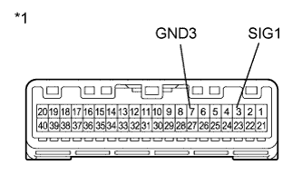
Text in Illustration *1 Component without harness connected
(Map Light Assembly)
Inspect the operation of the telephone switch assembly.
-
Measure the resistance according to the value(s) in the table below.
Standard Resistance Tester Connection Condition Specified Condition 3 (SIG1) - 7 (GND3) Telephone switch assembly not operated 410 to 414 Ω 3 (SIG1) - 7 (GND3) Telephone switch assembly operated 81 to 83 Ω
-
-
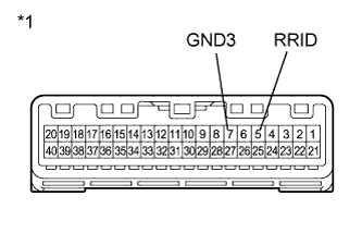
Text in Illustration *1 Component without harness connected
(Map Light Assembly)
Inspect the illumination for the telephone switch assembly.
-
Connect 4 1.5 V dry-cell batteries in series.
-
Connect the positive lead from the batteries to terminal 5 (RRID), and the negative lead to terminal 7 (GND3) of the map light assembly connector.
-
Check if the illumination for the telephone switch assembly comes on.
OK Illumination for the telephone switch assembly comes on.
-
-
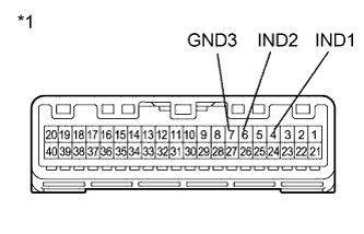
Text in Illustration *1 Component without harness connected
(Map Light Assembly)
Inspect the indicator of the telephone switch assembly.
-
Connect 2 dry-cell batteries in series.
-
Connect a positive (+) lead to terminal 4 (IND1) or 6 (IND2), and a negative (-) lead to terminal 7 (GND3) of the map light assembly connector.
-
Check if the illumination for the telephone switch assembly comes on.
OK The red indicator comes on when the positive (+) lead from the batteries is connected to terminal 4 (IND1) and the negative (-) lead is connected to terminal 7 (GND3). The green indicator comes on when the positive (+) lead from the batteries is connected to terminal 6 (IND2) and the negative (-) lead to is connected to terminal 7 (GND3).
-
-