LIGHTING SYSTEM Instrument Panel Illumination Circuit
DESCRIPTION
-
When the taillights are turned on by the automatic light control or manual light control, the instrument panel illumination is also turned on.
-
When the taillights are turned on by the daytime running light control, the instrument panel illumination ON is prohibited.
WIRING DIAGRAM
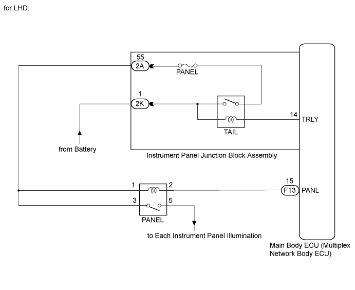
INSPECTION PROCEDURE
PROCEDURE
-
PERFORM ACTIVE TEST USING INTELLIGENT TESTER
-
Connect the intelligent tester to the DLC3.
-
Turn power switch on (IG).
-
Turn the intelligent tester on.
-
Enter the following menus: Body / Main Body / Active Test.
-
Check that the relay operate.
Main Body Tester Display Test Part Control Range Diagnostic Note Interior Panel Relay Interior panel relay ON/OFF Power switch is off and light control switch in tail position. OK Relay operates (each light comes on or off).
NG 
INSPECT RUNNING LIGHT RELAY (PANEL) Click here
OK 
PROCEED TO NEXT SUSPECTED AREA SHOWN IN PROBLEM SYMPTOMS TABLE Click here
-
-
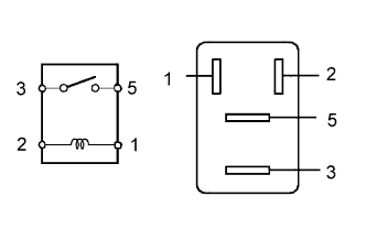
INSPECT RUNNING LIGHT RELAY (PANEL)
-
Remove the PANEL relay from the No. 1 relay block.
-
Measure the resistance according to the value(s) in the table below.
Standard Resistance Tester Connection Condition Specified Condition 3 - 5 Voltage is not applied between terminals 1 and 2 10 kΩ or higher 3 - 5 Voltage is applied between terminals 1 and 2 Below 1 Ω
NG 
REPLACE RUNNING LIGHT RELAY
OK 
-
-
CHECK HARNESS AND CONNECTOR (BATTERY - PANEL RELAY)
-
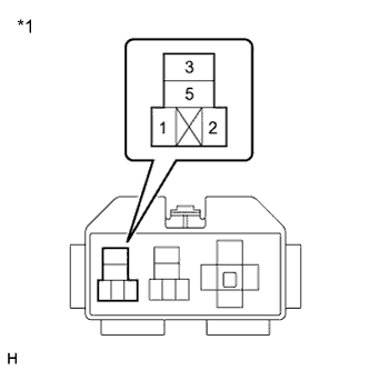
Text in Illustration *1 No. 1 Relay Block Measure the voltage according to the value(s) in the table below.
Standard Voltage Tester Connection Condition Specified Condition Relay terminal 1 - Body ground Light control switch off → tail Below 1 V → 11 to 14 V Relay terminal 3 - Body ground Light control switch off → tail Below 1 V → 11 to 14 V
NG
REPAIR OR REPLACE HARNESS OR CONNECTOR
OK
-
-
CHECK HARNESS AND CONNECTOR (PANEL RELAY - MAIN BODY ECU)
-
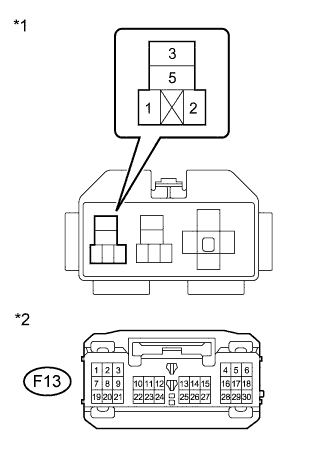
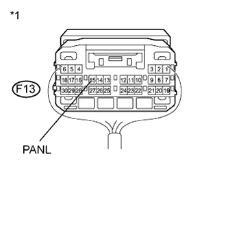
Text in Illustration *1 No. 1 Relay Block *2 Front view of wire harness connector
(to Main Body ECU (Multiplex Network Body ECU))
Disconnect the F13 main body ECU (multiplex network body ECU) connector.
-
Measure the resistance according to the value(s) in the table below.
Standard Resistance Tester Connection Condition Specified Condition Instrument panel illumination relay terminal 2 - F13-15 (PANL) Always Below 1 Ω F13-15 (PANL) - Body ground Always 10 kΩ or higher
NG
REPAIR OR REPLACE HARNESS OR CONNECTOR
OK
-
-
INSPECT MAIN BODY ECU (MULTIPLEX NETWORK BODY ECU)
-
Text in Illustration *1 Component with harness connected
(Main Body ECU (Multiplex Network Body ECU))
Reconnect the F13 main body ECU (multiplex network body ECU) connector.
-
Measure the voltage according to the value(s) in the table below.
Standard Voltage Tester Connection Condition Specified Condition F13-15 (PANL) - Body ground Light control switch in tail Below 1 V Light control switch in AUTO and taillights are on Below 1 V Taillights are turned on by the daytime running light control 11 to 14 V
NG
REPLACE MAIN BODY ECU (MULTIPLEX NETWORK BODY ECU) Click here
OK
REPAIR OR REPLACE HARNESS OR CONNECTOR (RELAY - EACH INSTRUMENT PANEL ILLUMINATION)
-