LIGHTING SYSTEM Overhead Console Illumination Light Circuit
DESCRIPTION
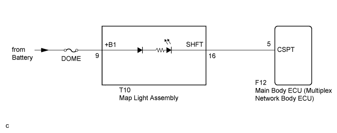
The main body ECU (multiplex network body ECU) controls the center console spot light.
WIRING DIAGRAM
INSPECTION PROCEDURE
PROCEDURE
-
PERFORM ACTIVE TEST USING INTELLIGENT TESTER
-
Connect the intelligent tester to the DLC3.
-
Turn the power switch on (IG).
-
Turn the intelligent tester on.
-
Enter the following menus: Body / Main Body / Active Test.
-
Check that the center console spot light comes on.
Main Body Tester Display Test Part Control Range Diagnostic Note Center Console Spot LGT Center console spot light ON/OFF Power switch off OK Center console spot light comes on.
NG 
INSPECT MAP LIGHT ASSEMBLY Click here
OK 
PROCEED TO NEXT SUSPECTED AREA SHOWN IN PROBLEM SYMPTOMS TABLE Click here
-
-
INSPECT MAP LIGHT ASSEMBLY
-
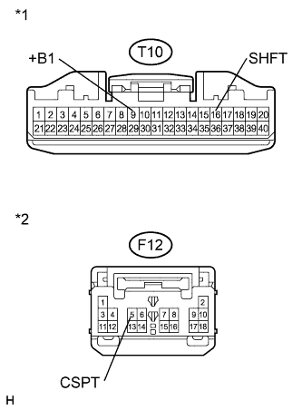
Text in Illustration *1 Component without harness connected
(Map Light Assembly)
Remove the map light assembly Click here.
-
Connect a positive (+) lead from the battery to terminal 9 and a negative (-) lead to terminal 16.
-
Check that the center console spot light comes on.
OK Center console spot light comes on.
NG 
REPLACE MAP LIGHT ASSEMBLY Click here
OK 
-
-
CHECK HARNESS AND CONNECTOR (MAP LIGHT ASSEMBLY - MAIN BODY ECU AND BODY GROUND)
-
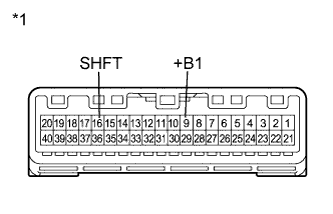
Text in Illustration *1 Front view of wire harness connector
(to Map Light Assembly)
*2 Front view of wire harness connector
(to Main Body ECU (Multiplex Network Body ECU))
Disconnect the T10 map light assembly connector.
-
Disconnect the F12 main body ECU (multiplex network body ECU) connector.
-
Measure the resistance according to the value(s) in the table below.
Standard Resistance Tester Connection Condition Specified Condition T10-16 (SHFT) - F12-5 (CSPT) Always Below 1 Ω T10-16 (SHFT) - Body ground Always 10 kΩ or higher -
Measure the voltage according to the value(s) in the table below.
Standard Voltage Tester Connection Condition Specified Condition T10-9 (+B1) - Body ground Always 11 to 14 V
NG
REPAIR OR REPLACE HARNESS OR CONNECTOR
OK
REPLACE MAIN BODY ECU (MULTIPLEX NETWORK BODY ECU) Click here
-