LIGHTING SYSTEM Interior Light Switch Signal Circuit
DESCRIPTION
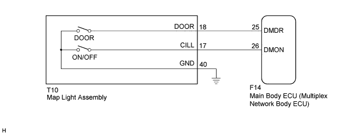
The main body ECU (multiplex network body ECU) detects the condition of the interior light door switch and interior light on/off switch.
WIRING DIAGRAM
INSPECTION PROCEDURE
PROCEDURE
-
READ VALUE USING INTELLIGENT TESTER
-
Connect the intelligent tester to the DLC3.
-
Turn the power switch on (IG).
-
Turn the intelligent tester on.
-
Enter the following menus: Body / Main Body / Data List.
-
Read the display on the intelligent tester.
Body (Main Body ECU RH) Tester Display Measurement Item/Range Normal Condition Diagnostic Note Dome Light DOOR SW Interior light door switch signal/ON or OFF ON: Interior light door switch not pushed
OFF: Interior light door switch pushed
- Dome Light SW Interior light on/off switch signal/ON or OFF ON: Interior light on/off switch pushed
OFF: Interior light on/off switch not pushed
- OK Switch condition can be displayed. Result Result Proceed to Interior light door switch does not operate A Interior light on/off switch does not operate B Both interior light door switch and on/off switch do not operate C OK D
A 
INSPECT MAP LIGHT ASSEMBLY Click here
B
INSPECT MAP LIGHT ASSEMBLY Click here
C
INSPECT MAP LIGHT ASSEMBLY Click here
D 
PROCEED TO NEXT SUSPECTED AREA SHOWN IN PROBLEM SYMPTOMS TABLE Click here
-
-
INSPECT MAP LIGHT ASSEMBLY
-
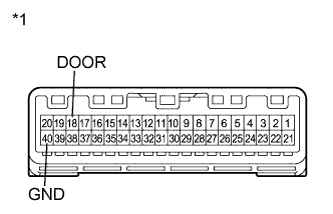
Text in Illustration *1 Component without harness connected:
(Map Light Assembly)
Remove the map light assembly Click here.
-
Measure the resistance according to the value(s) in the table.
Standard Resistance Tester Connection Condition Specified Condition 18 (DOOR) - 40 (GND) Interior light door switch pushed 10 kΩ or higher Interior light door switch not pushed Below 1 Ω
NG 
REPLACE MAP LIGHT ASSEMBLY Click here
OK 
-
-
CHECK HARNESS AND CONNECTOR (MAP LIGHT ASSEMBLY - MAIN BODY ECU)
-
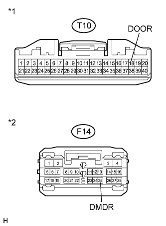
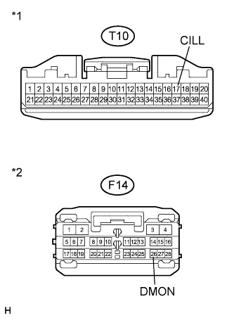
Text in Illustration *1 Front view of wire harness connector
(to Map Light Assembly)
*2 Front view of wire harness connector
(to Main Body ECU (Multiplex Network Body ECU))
Disconnect the T10 map light assembly connector.
-
Disconnect the F14 main body ECU (multiplex network body ECU) connector.
-
Measure the resistance according to the value(s) in the table.
Standard Resistance Tester Connection Condition Specified Condition T10-18 (DOOR) - F14-25 (DMDR) Always Below 1 Ω T10-18 (DOOR) - Body ground Always 10 kΩ or higher
NG
REPAIR OR REPLACE HARNESS OR CONNECTOR
OK
REPLACE MAIN BODY ECU (MULTIPLEX NETWORK BODY ECU) Click here
-
-
INSPECT MAP LIGHT ASSEMBLY
-
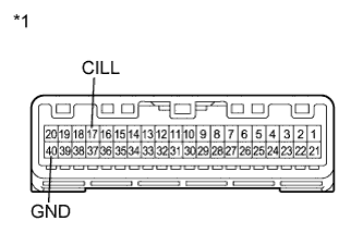
Text in Illustration *1 Component without harness connected:
(Map Light Assembly)
Remove the map light assembly Click here.
-
Measure the resistance according to the value(s) in the table.
Standard Resistance Tester Connection Condition Specified Condition 17 (CILL) - 40 (GND) Interior light on/off switch not pushed 10 kΩ or higher Interior light on/off switch pushed Below 1 Ω
NG
REPLACE MAP LIGHT ASSEMBLY Click here
OK
-
-
CHECK HARNESS AND CONNECTOR (MAP LIGHT ASSEMBLY - MAIN BODY ECU)
-
Text in Illustration *1 Front view of wire harness connector
(to Map Light Assembly)
*2 Front view of wire harness connector
(to Main Body ECU (Multiplex Network Body ECU))
Disconnect the map light assembly connector.
-
Disconnect the main body ECU (multiplex network body ECU) connector.
-
Measure the resistance according to the value(s) in the table.
Standard Resistance Tester Connection Condition Specified Condition T10-17 (CILL) - F14-26 (DMON) Always Below 1 Ω T10-17 (CILL) - Body ground Always 10 kΩ or higher
NG
REPAIR OR REPLACE HARNESS OR CONNECTOR
OK
REPLACE MAIN BODY ECU (MULTIPLEX NETWORK BODY ECU) Click here
-
-
INSPECT MAP LIGHT ASSEMBLY
-
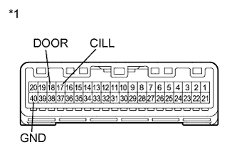
Text in Illustration *1 Component without harness connected:
(Map Light Assembly)
Remove the map light assembly Click here.
-
Measure the resistance according to the value(s) in the table.
Standard Resistance Tester Connection Condition Specified Condition 18 (DOOR) - 40 (GND) Interior light door switch pushed 10 kΩ or higher Interior light door switch not pushed Below 1 Ω 17 (CILL) - 40 (GND) Interior light on/off switch not pushed 10 kΩ or higher Interior light on/off switch pushed Below 1 Ω
NG
REPLACE MAP LIGHT ASSEMBLY Click here
OK
REPAIR OR REPLACE HARNESS OR CONNECTOR (MAP LIGHT ASSEMBLY - BODY GROUND)
-