LIGHTING SYSTEM Door Courtesy Light Circuit
DESCRIPTION
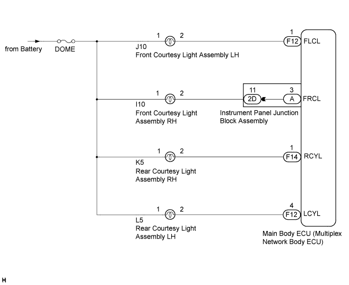
The main body ECU (multiplex network body ECU) receives the door courtesy light switch signal to control the courtesy light.
WIRING DIAGRAM
INSPECTION PROCEDURE
PROCEDURE
-
CHECK OPERATION
-
Check the operation of each courtesy light.
Result Result Proceed to Front courtesy light LH does not comes on A Front courtesy light RH does not comes on B Rear courtesy light LH does not comes on C Rear courtesy light RH does not comes on D
B 
CHECK HARNESS AND CONNECTOR (BATTERY - INSTRUMENT PANEL JUNCTION BLOCK ASSEMBLY) Click here
C
CHECK HARNESS AND CONNECTOR (BATTERY - MAIN BODY ECU (MULTIPLEX NETWORK BODY ECU)) Click here
D
CHECK HARNESS AND CONNECTOR (BATTERY - MAIN BODY ECU (MULTIPLEX NETWORK BODY ECU)) Click here
A 
-
-
CHECK HARNESS AND CONNECTOR (BATTERY - MAIN BODY ECU (MULTIPLEX NETWORK BODY ECU))
-
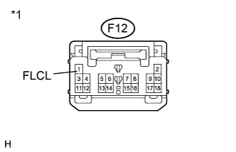
Text in Illustration *1 Front view of wire harness connector
(to Main Body ECU (Multiplex Network Body ECU))
Disconnect the F12 main body ECU (multiplex network body ECU) connector.
-
Measure the voltage according to the value(s) in the table below.
Standard Voltage Tester Connection Condition Specified Condition F12-1 (FLCL) - Body ground Always 11 to 14 V
NG 
REPAIR OR REPLACE HARNESS OR CONNECTOR
OK 
PROCEED TO NEXT SUSPECTED AREA SHOWN IN PROBLEM SYMPTOMS TABLE Click here
-
-
CHECK HARNESS AND CONNECTOR (BATTERY - INSTRUMENT PANEL JUNCTION BLOCK ASSEMBLY)
-
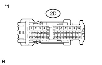
Text in Illustration *1 Front view of wire harness connector
(to Instrument Panel Junction Block Assembly)
Disconnect the 2D instrument panel junction block assembly connector.
-
Measure the voltage according to the value(s) in the table below.
Standard Voltage Tester Connection Condition Specified Condition 2D-11 - Body ground Always 11 to 14 V
NG
REPAIR OR REPLACE HARNESS OR CONNECTOR
OK
-
-
INSPECT INSTRUMENT PANEL JUNCTION BLOCK ASSEMBLY
-
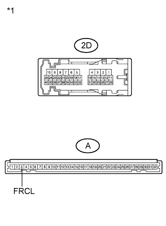
Text in Illustration *1 Component without harness connected
(Instrument Panel Junction Block Assembly)
Remove the instrument panel junction block assembly.
-
Measure the resistance according to the value(s) in the table below.
Standard Resistance Tester Connection Condition Specified Condition 2D-11 - A-3 (FRCL) Always Below 1 Ω 2D-11 - Body ground Always 10 kΩ or higher -
Check that the courtesy light comes on.
OK Courtesy light comes on.
NG
REPLACE INSTRUMENT PANEL JUNCTION BLOCK ASSEMBLY
OK
PROCEED TO NEXT SUSPECTED AREA SHOWN IN PROBLEM SYMPTOMS TABLE Click here
-
-
CHECK HARNESS AND CONNECTOR (BATTERY - MAIN BODY ECU (MULTIPLEX NETWORK BODY ECU))
-
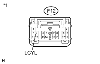
Text in Illustration *1 Front view of wire harness connector
(to Main Body ECU (Multiplex Network Body ECU))
Disconnect the F12 main body ECU (multiplex network body ECU) connector.
-
Measure the voltage according to the value(s) in the table below.
Standard Voltage Tester Connection Condition Specified Condition F12-4 (LCYL) - Body ground Always 11 to 14 V
NG
REPAIR OR REPLACE HARNESS OR CONNECTOR
OK
PROCEED TO NEXT SUSPECTED AREA SHOWN IN PROBLEM SYMPTOMS TABLE Click here
-
-
CHECK HARNESS AND CONNECTOR (BATTERY - MAIN BODY ECU (MULTIPLEX NETWORK BODY ECU))
-
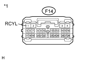
Text in Illustration *1 Front view of wire harness connector
(to Main Body ECU (Multiplex Network Body ECU))
Disconnect the F14 main body ECU (multiplex network body ECU) connector.
-
Measure the voltage according to the value(s) in the table below.
Standard Voltage Tester Connection Condition Specified Condition F14-1 (RCYL) - Body ground Always 11 to 14 V
NG
REPAIR OR REPLACE HARNESS OR CONNECTOR
OK
PROCEED TO NEXT SUSPECTED AREA SHOWN IN PROBLEM SYMPTOMS TABLE Click here
-