LIGHTING SYSTEM Door Courtesy Switch Circuit
DESCRIPTION
The main body ECU (multiplex network body ECU) detects the condition of the door courtesy light switch.
WIRING DIAGRAM
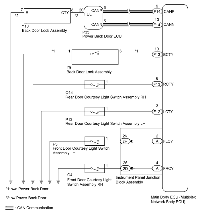
INSPECTION PROCEDURE
PROCEDURE
-
READ VALUE USING INTELLIGENT TESTER
-
Connect the intelligent tester to the DLC3.
-
Turn the power switch on (IG).
-
Turn the intelligent tester on.
-
Enter the following menus: Body / Main Body or Back Door / Data List.
-
Read the display on the intelligent tester.
Main Body Tester Display Measurement Item/Range Normal Condition Diagnostic Note FL Door Courtesy Front door LH condition signal/ON or OFF ON: Front door LH closed
OFF: Front door LH open
- FR Door Courtesy Front door RH condition signal/ON or OFF ON: Front door RH closed
OFF: Front door RH open
- RR Door Courtesy SW Rear door courtesy light switch RH signal/ON or OFF ON: Rear door RH open
OFF: Rear door RH closed
- RL Door Courtesy SW Rear door courtesy light switch LH signal/ON or OFF ON: Rear door LH open
OFF: Rear door LH closed
- Back Door Courtesy SW Back door courtesy switch signal/ON or OFF ON: Back door open
OFF: Back door closed
- Back Door (w/ Power Back Door) Tester Display Measurement Item/Range Normal Condition Diagnostic Note Courtesy SW Back door Courtesy switch signal/ON or OFF ON: Back door open
OFF: Back door closed
- OK Normal conditions listed above are displayed. Result Result Proceed to OK A Front door courtesy light switch LH or RH does not operate B Rear door courtesy light switch LH or RH does not operate C Back door courtesy switch does not operate D
B 
INSPECT FRONT DOOR COURTESY LIGHT SWITCH ASSEMBLY (LH OR RH) Click here
C
INSPECT REAR DOOR COURTESY LIGHT SWITCH ASSEMBLY (LH OR RH) Click here
D
INSPECT BACK DOOR LOCK ASSEMBLY Click here
A 
PROCEED TO NEXT SUSPECTED AREA SHOWN IN PROBLEM SYMPTOMS TABLE Click here
-
-
INSPECT FRONT DOOR COURTESY LIGHT SWITCH ASSEMBLY (LH OR RH)
-
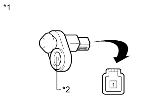
Text in Illustration *1 Component without harness connected
(Front Door Courtesy Light Switch Assembly)
*2 Switch Body Remove the front door courtesy light switch assembly Click here.
-
Measure the resistance according to the value(s) in the table below.
Standard Resistance Tester Connection Switch Condition Specified Condition 1 - Switch body Pushed 10 kΩ or higher 1 - Switch body Not pushed Below 1 Ω
NG 
REPLACE FRONT DOOR COURTESY LIGHT SWITCH ASSEMBLY Click here
OK 
-
-
CHECK HARNESS AND CONNECTOR (INSTRUMENT PANEL JUNCTION BLOCK ASSEMBLY - SWITCH)
-
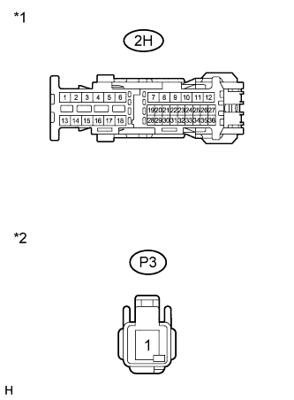
Text in Illustration *1 Front view of wire harness connector
(to Instrument Panel Junction Block Assembly)
*2 Front view of wire harness connector
(to Front Door Courtesy Light Switch Assembly)
for Front LH
-
Disconnect the 2H instrument panel junction block assembly connector.
-
Disconnect the P3 front door courtesy light switch assembly connector.
-
Measure the resistance according to the value(s) in the table below.
Standard Resistance Tester Connection Condition Specified Condition 2H-26 - P3-1 Always Below 1 Ω 2H-26 - Body ground Always 10 kΩ or higher
-
-
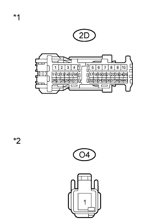
Text in Illustration *1 Front view of wire harness connector
(to Instrument Panel Junction Block Assembly)
*2 Front view of wire harness connector
(to Front Door Courtesy Light Switch Assembly)
for Front RH
-
Disconnect the 2D instrument panel junction block assembly connector.
-
Disconnect the O4 front door courtesy light switch assembly connector.
-
Measure the resistance according to the value(s) in the table below.
Standard Resistance Tester Connection Condition Specified Condition 2D-26 - O4-1 Always Below 1 Ω 2D-26 - Body ground Always 10 kΩ or higher
-
NG
REPAIR OR REPLACE HARNESS OR CONNECTOR
OK
-
-
INSPECT INSTRUMENT PANEL JUNCTION BLOCK ASSEMBLY
-
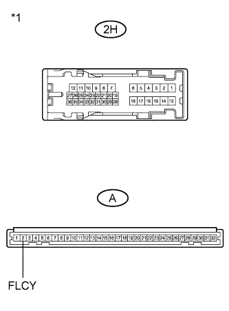
Text in Illustration *1 Component without harness connected
(Instrument Panel Junction Block Assembly)
for Front LH
-
Remove the instrument panel junction block assembly.
-
Measure the resistance according to the value(s) in the table below.
Standard Resistance Tester Connection Condition Specified Condition 2H-26 - A-2 (FLCY) Always Below 1 Ω 2H-26 - Body ground Always 10 kΩ or higher
-
-
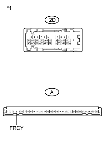
Text in Illustration *1 Component without harness connected
(Instrument Panel Junction Block Assembly)
for Front RH
-
Remove the instrument panel junction block assembly.
-
Measure the resistance according to the value(s) in the table below.
Standard Resistance Tester Connection Condition Specified Condition 2D-26 - A-4 (FRCY) Always Below 1 Ω 2D-26 - Body ground Always 10 kΩ or higher
-
NG
REPLACE INSTRUMENT PANEL JUNCTION BLOCK ASSEMBLY
OK
REPLACE MAIN BODY ECU (MULTIPLEX NETWORK BODY ECU) Click here
-
-
INSPECT REAR DOOR COURTESY LIGHT SWITCH ASSEMBLY (LH OR RH)
-
Text in Illustration *1 Component without harness connected
(Rear Door Courtesy Light Switch Assembly)
*2 Switch Body Remove the rear door courtesy light switch assembly Click here.
-
Measure the resistance according to the value(s) in the table below.
Standard Resistance Tester Connection Switch Condition Specified Condition 1 - Switch body Pushed 10 kΩ or higher 1 - Switch body Not pushed Below 1 Ω
NG
REPLACE REAR DOOR COURTESY LIGHT SWITCH ASSEMBLY Click here
OK
-
-
CHECK HARNESS AND CONNECTOR (MAIN BODY ECU - REAR COURTESY LIGHT SWITCH)
-
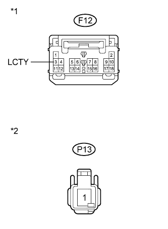
Text in Illustration *1 Front view of wire harness connector
(to Main Body ECU (Multiplex Network Body ECU))
*2 Front view of wire harness connector
(to Rear Door Courtesy Light Switch Assembly)
for Rear LH
-
Disconnect the F12 main body ECU (multiplex network body ECU) connector.
-
Disconnect the P13 rear door courtesy light switch assembly connector.
-
Measure the resistance according to the value(s) in the table below.
Standard Resistance Tester Connection Condition Specified Condition F12-3 (LCTY) - P13-1 Always Below 1 Ω F12-3 (LCTY) - Body ground Always 10 kΩ or higher
-
-
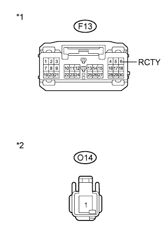
Text in Illustration *1 Front view of wire harness connector
(to Main Body ECU (Multiplex Network Body ECU))
*2 Front view of wire harness connector
(to Rear Door Courtesy Light Switch Assembly)
for Rear RH
-
Disconnect the F13 main body ECU (multiplex network body ECU) connector.
-
Disconnect the O14 rear door courtesy light switch assembly connector.
-
Measure the resistance according to the value(s) in the table below.
Standard Resistance Tester Connection Condition Specified Condition F13-6 (RCTY) - O14-1 Always Below 1 Ω F13-6 (RCTY) - Body ground Always 10 kΩ or higher
-
NG
REPAIR OR REPLACE HARNESS OR CONNECTOR
OK
REPLACE MAIN BODY ECU (MULTIPLEX NETWORK BODY ECU) Click here
-
-
INSPECT BACK DOOR LOCK ASSEMBLY
-
w/o Power Back Door
-
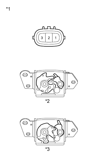
Text in Illustration *1 Component without harness connected
(Back Door Lock Assembly)
*2 Lock *3 Unlock Remove the back door lock assembly Click here.
-
Measure the resistance according to the value(s) in the table below.
Standard Resistance Tester Connection Switch Condition Specified Condition 1 - 3 Locked 10 kΩ or higher 1 - 3 Unlocked Below 1 Ω
-
-
w/ Power Back Door
-
Remove the back door lock assembly Click here.
-
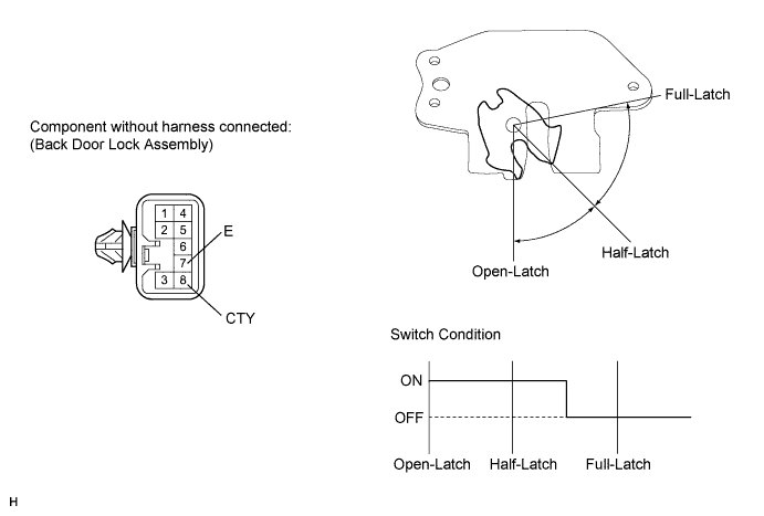
Measure the resistance according to the value(s) in the table below.
Standard Resistance Tester Connection Condition Specified Condition 8 (CTY) - 7 (E) Open-latch Below 1 Ω 8 (CTY) - 7 (E) Half-latch Below 1 Ω 8 (CTY) - 7 (E) Full-latch 10 kΩ or higher 8 (CTY) - 7 (E) Over-latch 10 kΩ or higher
-
NG
REPLACE BACK DOOR LOCK ASSEMBLY Click here
OK
-
-
CHECK HARNESS AND CONNECTOR (BACK DOOR LOCK - MAIN BODY ECU OR POWER BACK DOOR UNIT)
-
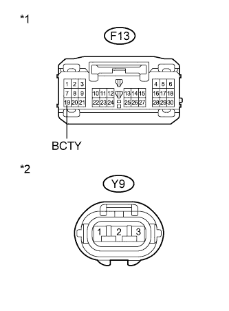
Text in Illustration *1 Front view of wire harness connector
(to Main Body ECU (Multiplex Network Body ECU))
*2 Front view of wire harness connector
(to Back Door Lock Assembly)
w/o Power Back Door
-
Disconnect the F13 main body ECU (multiplex network body ECU) connector.
-
Disconnect the Y9 back door lock assembly connector.
-
Measure the resistance according to the value(s) in the table below.
Standard Resistance Tester Connection Condition Specified Condition F13-19 (BCTY) - Y9-3 Always Below 1 Ω F13-19 (BCTY) - Body ground Always 10 kΩ or higher Y9-1 - Body ground Always Below 1 Ω
-
-
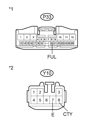
Text in Illustration *1 Front view of wire harness connector
(to Power Back Door Unit Assembly)
*2 Front view of wire harness connector
(to Back Door Lock Assembly)
w/ Power Back Door
-
Disconnect the P33 power back door unit assembly connector.
-
Disconnect the Y10 back door lock assembly connector.
-
Measure the resistance according to the value(s) in the table below.
Standard Resistance Tester Connection Condition Specified Condition P33-20 (FUL) - Y10-8 (CTY) Always Below 1 Ω P33-20 (FUL) - Body ground Always 10 kΩ or higher Y10-7 (E) - Body ground Always Below 1 Ω Result Result Proceed to OK (w/o Power Back Door) A OK (w/ Power Back Door) B NG C
-
B
REPLACE POWER BACK DOOR UNIT ASSEMBLY Click here
C
REPAIR OR REPLACE HARNESS OR CONNECTOR
A
REPLACE MAIN BODY ECU (MULTIPLEX NETWORK BODY ECU) Click here
-