LIGHTING SYSTEM Door Unlock Detection Switch Circuit
DESCRIPTION
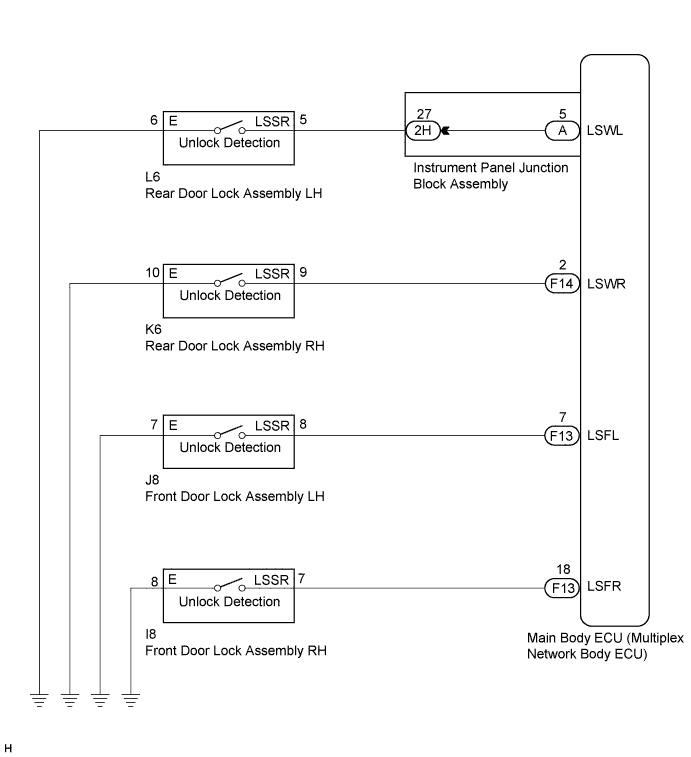
The main body ECU (multiplex network body ECU) detects the condition of the door unlock detection switch.
WIRING DIAGRAM
INSPECTION PROCEDURE
PROCEDURE
-
READ VALUE USING INTELLIGENT TESTER
-
Connect the intelligent tester to the DLC3.
-
Turn the power switch on (IG).
-
Turn the intelligent tester on.
-
Enter the following menus: Body / Main Body / Data List.
-
Read the display on the intelligent tester.
Main Body Tester Display Measurement Item/Range Normal Condition Diagnostic Note FL Door Lock Pos Front door unlock detection switch LH signal/ON or OFF ON: Front door LH unlocked
OFF: Front door LH locked
- FR Door Lock Pos Front door unlock detection switch RH signal/ON or OFF ON: Front door RH unlocked
OFF: Front door RH locked
- RL-Door Lock Pos SW Rear door unlock detection switch LH signal/ON or OFF ON: Rear door LH unlocked
OFF: Rear door LH locked
- RR-Door Lock Pos SW Rear door unlock detection switch RH signal/ON or OFF ON: Rear door RH unlocked
OFF: Rear door RH locked
- Result Result Proceed to OK A Front door unlock detection switch LH does not operate B Front door unlock detection switch RH does not operate C Rear door unlock detection switch LH does not operate D Rear door unlock detection switch RH does not operate E
B 
INSPECT FRONT DOOR LOCK ASSEMBLY LH Click here
C
INSPECT FRONT DOOR LOCK ASSEMBLY RH Click here
D
INSPECT REAR DOOR LOCK ASSEMBLY LH Click here
E
INSPECT REAR DOOR LOCK ASSEMBLY RH Click here
A 
PROCEED TO NEXT SUSPECTED AREA SHOWN IN PROBLEM SYMPTOMS TABLE Click here
-
-
INSPECT FRONT DOOR LOCK ASSEMBLY LH
-
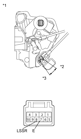
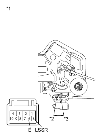
Text in Illustration *1 Component without harness connected
(Front Door Lock Assembly LH)
*2 Unlock *3 Lock Remove the front door lock assembly LH Click here.
-
Measure the resistance according to the value(s) in the table below.
Standard Resistance Tester Connection Condition Specified Condition 7 (E) - 8 (LSSR) Locked 10 kΩ or higher Unlocked Below 1 Ω
NG 
REPLACE FRONT DOOR LOCK ASSEMBLY LH Click here
OK 
-
-
CHECK HARNESS AND CONNECTOR (FRONT DOOR LOCK ASSEMBLY LH - MAIN BODY ECU AND BODY GROUND)
-
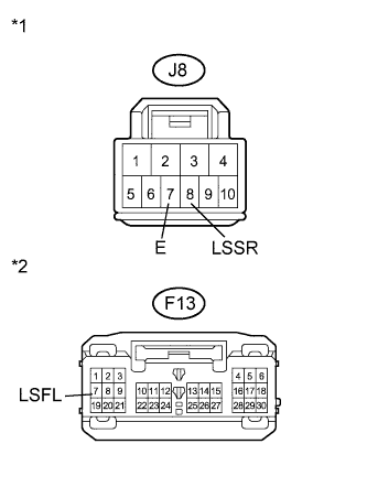
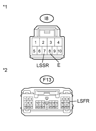
Text in Illustration *1 Front view of wire harness connector
(to Front Door Lock Assembly LH)
*2 Front view of wire harness connector
(to Main Body ECU (Multiplex Network Body ECU))
Disconnect the J8 front door lock assembly LH connector.
-
Disconnect the F13 main body ECU (multiplex network body ECU) connector.
-
Measure the resistance according to the value(s) in the table below.
Standard Resistance Tester Connection Condition Specified Condition J8-8 (LSSR) - F13-7 (LSFL) Always Below 1 Ω J8-8 (LSSR) - Body ground Always 10 kΩ or higher J8-7 (E) - Body ground Always Below 1 Ω
NG
REPAIR OR REPLACE HARNESS OR CONNECTOR
OK
REPLACE MAIN BODY ECU (MULTIPLEX NETWORK BODY ECU) Click here
-
-
INSPECT FRONT DOOR LOCK ASSEMBLY RH
-
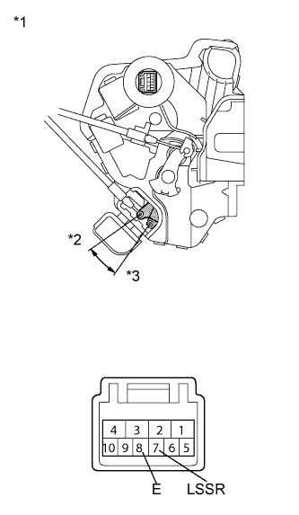
Text in Illustration *1 Component without harness connected
(Front Door Lock Assembly RH)
*2 Unlock *3 Lock Remove the front door lock assembly RH Click here.
-
Measure the resistance according to the value(s) in the table below.
Standard Resistance Tester Connection Condition Specified Condition 7 (LSSR) - 8 (E) Locked 10 kΩ or higher Unlocked Below 1 Ω
NG
REPLACE FRONT DOOR LOCK ASSEMBLY RH Click here
OK
-
-
CHECK HARNESS AND CONNECTOR (FRONT DOOR LOCK ASSEMBLY RH - MAIN BODY ECU AND BODY GROUND)
-
Text in Illustration *1 Front view of wire harness connector
(to Front Door Lock Assembly RH)
*2 Front view of wire harness connector
(to Main Body ECU (Multiplex Network Body ECU))
Disconnect the I8 front door lock assembly RH connector.
-
Disconnect the F13 main body ECU (multiplex network body ECU) connector.
-
Measure the resistance according to the value(s) in the table below.
Standard Resistance Tester Connection
(Symbols)
Condition Specified Condition I8-7 (LSSR) - F13-18 (LSFR) Always Below 1 Ω I8-7 (LSSR) - Body ground Always 10 kΩ or higher I8-8 (E) - Body ground Always Below 1 Ω
NG
REPAIR OR REPLACE HARNESS OR CONNECTOR
OK
REPLACE MAIN BODY ECU (MULTIPLEX NETWORK BODY ECU) Click here
-
-
INSPECT REAR DOOR LOCK ASSEMBLY LH
-
Text in Illustration *1 Component without harness connected
(Rear Door Lock Assembly LH)
*2 Lock *3 Unlock Remove the rear door lock assembly LH Click here.
-
Measure the resistance according to the value(s) in the table below.
Standard Resistance Tester Connection Condition Specified Condition 5 (LSSR) - 6 (E) Locked 10 kΩ or higher Unlocked Below 1 Ω
NG
REPLACE REAR DOOR LOCK ASSEMBLY LH Click here
OK
-
-
CHECK HARNESS AND CONNECTOR (REAR DOOR LOCK ASSEMBLY LH - MAIN BODY ECU AND BODY GROUND)
-
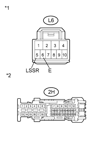
Text in Illustration *1 Front view of wire harness connector
(to Rear Door Lock Assembly LH)
*2 Front view of wire harness connector
(to Instrument Panel Junction Block Assembly)
Disconnect the L6 rear door lock assembly LH connector.
-
Disconnect the 2H instrument panel junction block assembly connector.
-
Measure the resistance according to the value(s) in the table below.
Standard Resistance Tester Connection Condition Specified Condition L6-5 (LSSR) - 2H-27 Always Below 1 Ω L6-5 (LSSR) - Body ground Always 10 kΩ or higher L6-6 (E) - Body ground Always Below 1 Ω
NG
REPAIR OR REPLACE HARNESS OR CONNECTOR
OK
-
-
INSPECT INSTRUMENT PANEL JUNCTION BLOCK ASSEMBLY
-
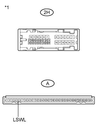
Text in Illustration *1 Component without harness connected
(Instrument Panel Junction Block Assembly)
Remove the instrument panel junction block assembly.
-
Measure the resistance according to the value(s) in the table below.
Standard Resistance Tester Connection Condition Specified Condition 2H-27 - A-5 (LSWL) Always Below 1 Ω 2H-27 - Body ground Always 10 kΩ or higher
NG
REPLACE INSTRUMENT PANEL JUNCTION BLOCK ASSEMBLY
OK
REPLACE MAIN BODY ECU (MULTIPLEX NETWORK BODY ECU) Click here
-
-
INSPECT REAR DOOR LOCK ASSEMBLY RH
-
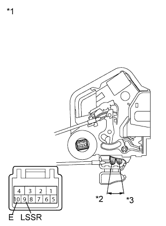
Text in Illustration *1 Component without harness connected
(Rear Door Lock Assembly RH)
*2 Lock *3 Unlock Remove the rear door lock assembly RH Click here.
-
Measure the resistance according to the value(s) in the table below.
Standard Resistance Tester Connection Door Lock Condition Specified Condition 9 (LSSR) - 10 (E) Locked 10 kΩ or higher Unlocked Below 1 Ω
NG
REPLACE REAR DOOR LOCK ASSEMBLY RH Click here
OK
-
-
CHECK HARNESS AND CONNECTOR (REAR DOOR LOCK ASSEMBLY RH - MAIN BODY ECU AND BODY GROUND)
-
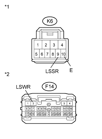
Text in Illustration *1 Front view of wire harness connector
(to Rear Door Lock Assembly RH)
*2 Front view of wire harness connector
(to Main Body ECU (Multiplex Network Body ECU))
Disconnect the K6 rear door lock assembly RH connector.
-
Disconnect the F14 main body ECU (multiplex network body ECU) connector.
-
Measure the resistance according to the value(s) in the table below.
Standard Resistance Tester Connection (Symbols) Condition Specified Condition K6-9 (LSSR) - F14-2 (LSWR) Always Below 1 Ω K6-9 (LSSR) - Body ground Always 10 kΩ or higher K6-10 (E) - Body ground Always Below 1 Ω
NG
REPAIR OR REPLACE HARNESS OR CONNECTOR
OK
REPLACE MAIN BODY ECU (MULTIPLEX NETWORK BODY ECU) Click here
-