SECURITY HORN ASSEMBLY (for Built-in Battery type) REMOVAL

-
PRECAUTION (w/ Navigation System for HDD)
Note
After the power switch is turned off, the display and navigation module display (HDD navigation system) records various types of memory and settings. As a result, after turning the power switch off, make sure to wait for the time specified in the following table before disconnecting the cable from the negative (-) battery terminal.
Waiting Time before Disconnecting Cable from Negative (-) Battery Terminal Specification Waiting Time w/o Telematics transceiver 60 sec. w/ Telematics transceiver 120 sec. -
REMOVE REAR DECK FLOOR BOX
-

Remove the 3 clips and the rear deck floor box.
-
-
DISCONNECT CABLE FROM NEGATIVE BATTERY TERMINAL
Note
When disconnecting the cable, some systems need to be initialized after the cable is reconnected Click here.
-
REMOVE REAR SEAT HEADREST ASSEMBLY RH
-
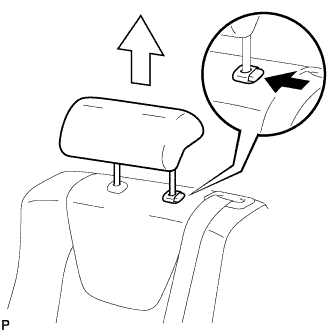
Press the headrest support button and pull up the headrest as shown in the illustration.
-
-
REMOVE REAR SEAT CENTER HEADREST ASSEMBLY
-
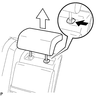
Press the headrest support button and pull up the headrest as shown in the illustration.
-
-
REMOVE REAR SEAT OUTER TRACK BRACKET COVER RH
-
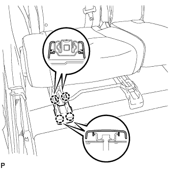
Disengage the 4 claws and remove the rear seat track bracket cover RH.
-
-
REMOVE REAR SEAT INNER TRACK BRACKET COVER RH
-
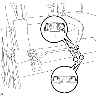
Disengage the 4 claws and remove the 4 rear seat track bracket cover RH.
-
-
DISCONNECT REAR SEAT LOCK CABLE ASSEMBLY RH
-
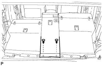
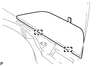
Using a clip remover, remove the 2 clips and disconnect the rear seatback board sub-assembly.
-
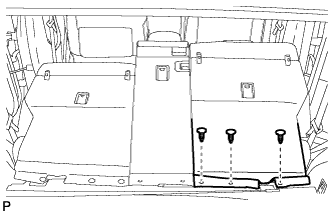
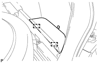
Using a clip remover, remove the 3 clips and disconnect the rear seatback board carpet assembly RH.
-
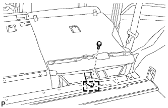
Remove the bolt.
-
Disengage the guide and disconnect the No. 1 fold seat stopper band assembly.
-
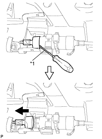
Pull down the adjusters lock piece to release the lock as shown in the illustration.
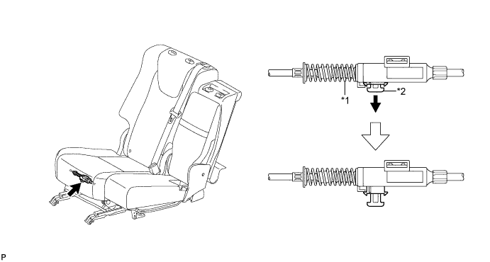
Text in Illustration *1 Adjusters Spring *2 Lock Piece -
Text in Illustration *1 Protective Tape Using a screwdriver wrapped with protective tape, disconnect the No. 1 reclining control cable as shown in the illustration.
-
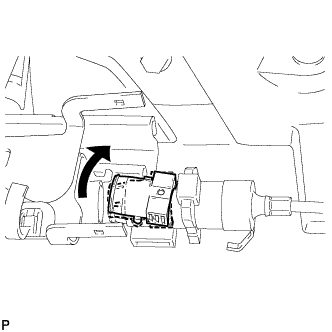
Remove the rear seat reclining control cable from the cover as shown in the illustration.
-
Lift up the seat track adjusting handle to the uppermost position and hold the handle in this position as shown in the illustration.
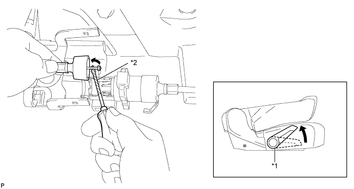
Text in Illustration *1 Seat Track Adjusting Handle *2 Protective Tape -
Using a screwdriver wrapped with protective tape, disconnect the No. 1 rear seat lock cable assembly as shown in the illustration.
-
Using a screwdriver wrapped with protective tape, disconnect the rear seat lock cable assembly RH as shown in the illustration.
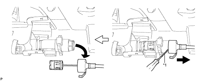
Text in Illustration *1 Protective Tape -
When replacing the rear seat assembly RH or rear seat reclining control cable with a new one:
-
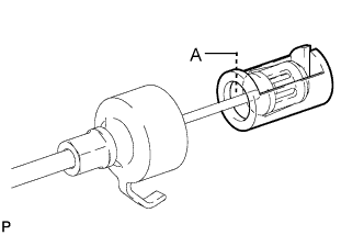
Cut portion A shown in the illustration to separate the rear seat assembly RH or rear seat reclining control cable.
-
-
When replacing the rear seat lock cable assembly RH with a new one:
-
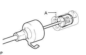
Cut portion A shown in the illustration to separate the rear seat lock assembly RH.
-
-
-
REMOVE REAR SEAT ASSEMBLY RH
-
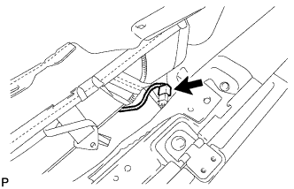
Disconnect the connector.
-
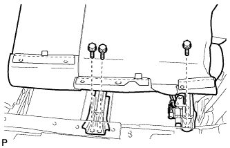
Remove the 3 bolts on the rear side of the seat.
-
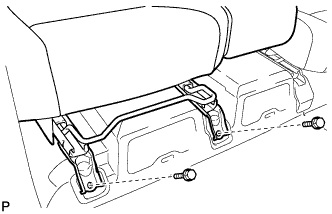
Remove the 2 bolts on the front side of the seat and the rear seat assembly RH.
Note
Be careful not to damage the vehicle body.
-
-
REMOVE DECK BOARD SUB-ASSEMBLY
-
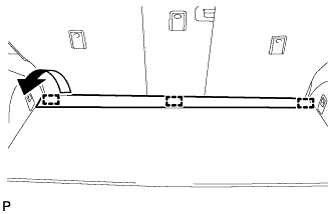
Disengage the 3 fasteners as shown in the illustration.
-
for Compact Spare Tire:
-
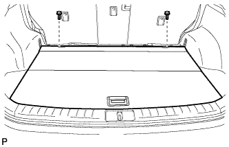
Remove the 2 bolts and remove the deck board sub-assembly.
-
-
for Full Size Spare Tire:
-
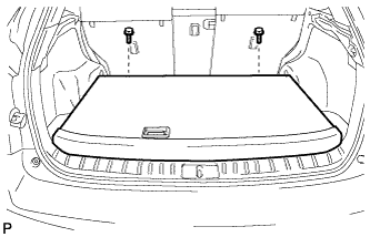
Remove the 2 bolts and remove the deck board sub-assembly.
-
-
-
REMOVE SPARE WHEEL COVER ASSEMBLY (for Compact Spare Tire)
-
Remove the spare wheel cover assembly.
-
-
REMOVE TONNEAU COVER ASSEMBLY
-
Remove the tonneau cover assembly.
-
-
REMOVE NO. 3 REAR FLOOR BOARD (for Compact Spare Tire)
-
Disengage the 2 guides and remove the No. 3 rear floor board.
-
-
REMOVE NO. 3 REAR FLOOR BOARD (for Full Size Spare Tire)
-
Disengage the 2 guides and remove the No. 3 rear floor board.
-
-
REMOVE DECK SIDE TRIM BOX RH (for Compact Spare Tire)
-
Remove the 2 clips and deck side trim box RH.
-
-
REMOVE DECK SIDE TRIM BOX RH (for Full Size Spare Tire)
-
Remove the 3 clips and the deck side trim box RH.
-
-
REMOVE REAR FLOOR FINISH PLATE
-
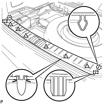
Disengage the 2 claws, 6 clips and 2 guides, and remove the rear floor finish plate.
-
-
REMOVE REAR FLOOR FINISH SIDE PLATE RH
Tech Tips
Use the same procedure for the RH side and LH side Click here.
-
REMOVE REAR DOOR SCUFF PLATE RH
Tech Tips
Use the same procedure for the RH side and LH side Click here.
-
REMOVE REAR SEAT SIDE COVER RH
Tech Tips
Use the same procedure for the RH side and LH side Click here.
-
REMOVE NO. 1 LUGGAGE COMPARTMENT TRIM HOOK
Tech Tips
Use the same procedure for the RH side and LH side Click here.
-
REMOVE ROPE HOOK ASSEMBLY
Tech Tips
Use the same procedure for the RH side and LH side Click here.
-
REMOVE RECLINING REMOTE CONTROL BEZEL RH
Tech Tips
Use the same procedure for the RH side and LH side Click here.
-
REMOVE HEIGHT CONTROL SWITCH (w/ Air Suspension)
-
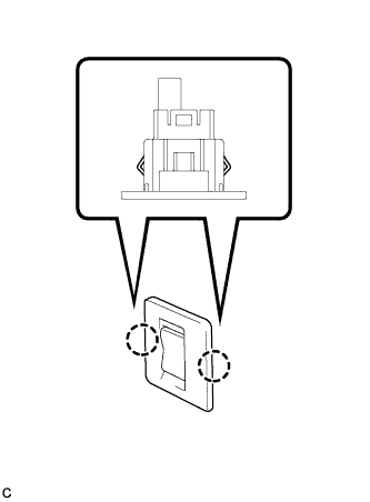
Disengage the 2 claws to remove the height control switch from the deck trim side panel assembly RH.
-
Disconnect the connector.
-
-
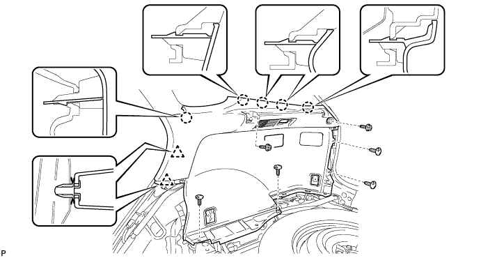
REMOVE DECK TRIM SIDE PANEL ASSEMBLY RH
-
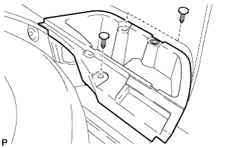
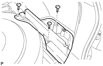
Remove the 2 screws.
-
Remove the 5 clips.
-
Disengage the 5 claws and 2 clips.
-
Disconnect the connector and remove the deck trim side panel assembly RH.
-
-
REMOVE THEFT WARNING SIREN ASSEMBLY
-
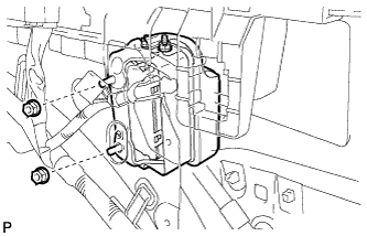
Remove the 2 nuts.
-
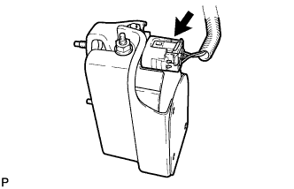
Disconnect the connector and remove the theft warning siren assembly.
-