THEFT DETERRENT SYSTEM (w/o Intrusion Sensor) TERMINALS OF ECU

-
CHECK MAIN BODY ECU (MULTIPLEX NETWORK BODY ECU)
-
Disconnect the main body ECU (multiplex network body ECU) connectors.
-
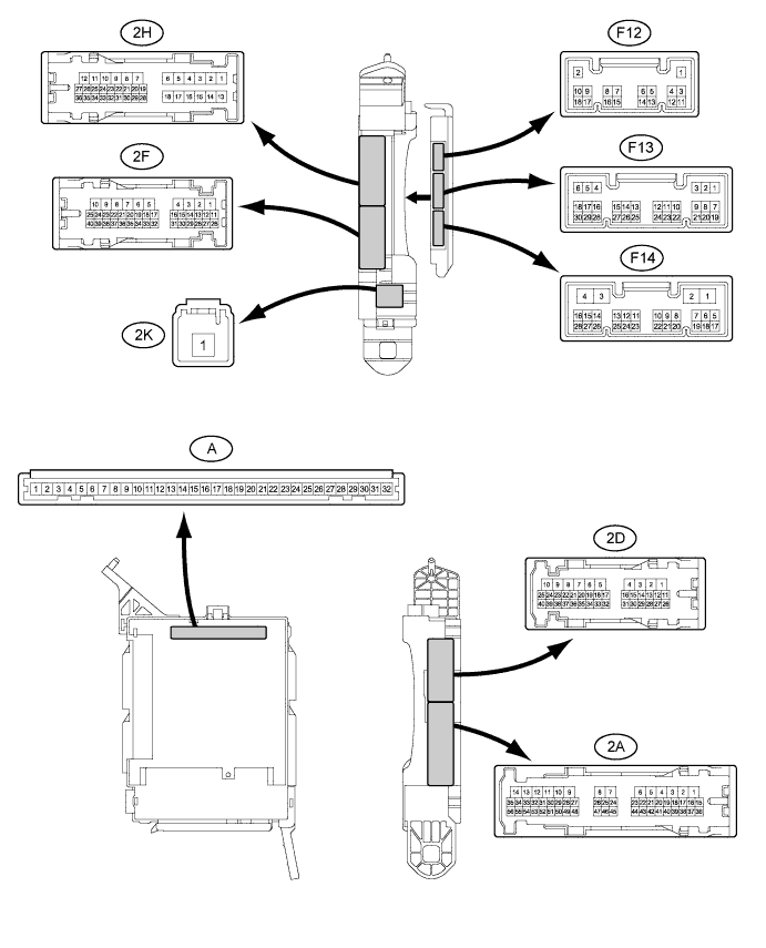
Measure the resistance and voltage according to the value(s) in the table below.
Tester Connection Wiring Color Terminal Description Condition Specified Condition F13-6 (RCTY) - Body ground GR - Body ground Rear courtesy light switch RH input Rear door RH closed (OFF) → open (ON) 10 kΩ or higher → Below 1 Ω F12-3 (LCTY) - Body ground L - Body ground Rear courtesy light switch LH input Rear door LH closed (OFF) → open (ON) 10 kΩ or higher → Below 1 Ω A-2 (FLCY) - Body ground - Front left door courtesy light switch input Front left door closed (OFF) → open (ON) 10 kΩ or higher → Below 1 Ω A-4 (FRCY) - Body ground - Front right door courtesy light switch input Front right door closed (OFF) → open (ON) 10 kΩ or higher → Below 1 Ω F13-19 (BCTY)* - Body ground R - Body ground Back door courtesy light switch input Back door closed (OFF) → open (ON) 10 kΩ or higher → Below 1 Ω A-29 (ACC) - Body ground - Ignition power supply (ACC signal) Power switch on (ACC) → off 11 to 14 V → Below 1 V A-31 (ALTB) - Body ground - +B (power system alternator system) power supply Power switch off 11 to 14 V A-32 (IG) - Body ground - Ignition power supply (IG signal) Power switch on (IG) → off 11 to 14 V → Below 1 V A-11 (GND1) - Body ground - Ground Always Below 1 Ω F14-3 (GND2) - Body ground W-B - Body ground Ground Always Below 1 Ω *: w/o Power Back Door System
Tech Tips
If the result is not as specified, there may be a malfunction in the wire harness.
-
Reconnect the main body ECU (multiplex network body ECU) connectors.
-
Measure the voltage and resistance according to the value(s) in the table below.
Tester Connection Wiring Color Terminal Description Condition Specified Condition F14-17 (HZSW) - Body ground Y - Body ground Turn signal flasher relay signal System in alarm sounding state Below 1 V F14-18 (SSCL)*1 - Body ground BR - Body ground Theft warning siren drive Theft warning siren sounding
(Theft deterrent system in alarm sounding state)
Pulse generation
(Below 1 V ← → 12 V)
A-28 (HORN) - Body ground - Vehicle horn drive Vehicle horn sounding
(Theft deterrent system in alarm sounding state)
Pulse generation
(Below 1 V ← → 12 V)
A-17 (SH)*2 - Body ground - Security horn drive Security horn sounding
(Theft deterrent system in alarm sounding state)
Pulse generation
(Below 1 V ← → 12 V)
A-20 (HCTY) - Body ground - Engine courtesy switch input Engine hood open (ON) → closed (OFF) Below 1 Ω → 10 kΩ or higher If the result is not as specified, the main body ECU (multiplex network body ECU) may have a malfunction.
-
*1: w/ Theft Warning Siren
-
*2: w/ Security Horn
-
-