THEFT DETERRENT SYSTEM (w/ Intrusion Sensor) Engine Hood Courtesy Switch Circuit
DESCRIPTION
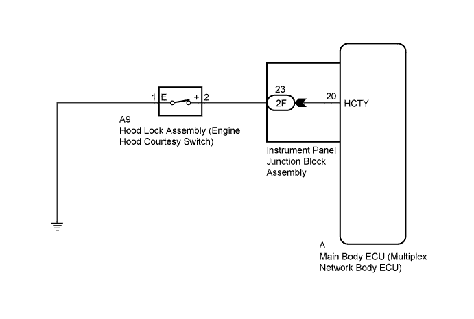
The engine hood courtesy switch is installed together with the hood lock. This switch turns on when the engine hood is opened and turns off when the engine hood is closed.
WIRING DIAGRAM
INSPECTION PROCEDURE
PROCEDURE
-
READ VALUE USING INTELLIGENT TESTER
-
Connect the intelligent tester to the DLC3.
-
Turn the power switch on (IG).
-
Turn the intelligent tester on.
-
Select the item below in the Data List and read the display on the intelligent tester.
Main Body Tester Display Measurement Item/Range Normal Condition Diagnostic Note Hood Courtesy SW Engine hood courtesy switch signal/ON or OFF ON: Engine hood open
OFF: Engine hood closed
- OK The indicator on the intelligent tester switches between ON and OFF in accordance with the engine hood courtesy switch status.
NG 
INSPECT INSTRUMENT PANEL JUNCTION BLOCK ASSEMBLY Click here
OK 
REPLACE MAIN BODY ECU (MULTIPLEX NETWORK BODY ECU) Click here
-
-
INSPECT INSTRUMENT PANEL JUNCTION BLOCK ASSEMBLY
-
Disconnect the 2F instrument panel junction block assembly and A main body ECU (multiplex network body ECU) connectors.
-
Measure the resistance according to the value(s) in the table below.
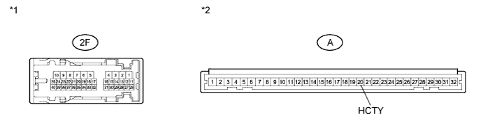
Standard Resistance Tester Connection Condition Specified Condition 2F-23 - A-20 (HCTY) Always Below 1 Ω Text in Illustration *1 Component without harness connected
(Instrument Panel Junction Block Assembly)
*2 Front view of wire harness connector
(to Main Body ECU (Multiplex Network Body ECU))
NG 
REPLACE INSTRUMENT PANEL JUNCTION BLOCK ASSEMBLY
OK 
-
-
INSPECT HOOD LOCK ASSEMBLY (ENGINE HOOD COURTESY SWITCH)
-
for LHD:
-
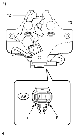
Text in Illustration *1 Component without harness connected
(Hood Lock Assembly (Engine Hood Courtesy Switch))
*2 Unlock *3 Lock Remove the hood lock assembly Click here.
-
Measure the resistance according to the value(s) in the table below.
Standard Resistance Tester Connection Switch Condition Specified Condition A9-1 (E) - A9-2 (+) Unlocked Below 1 Ω Locked 10 kΩ or higher
-
-
for RHD:
-
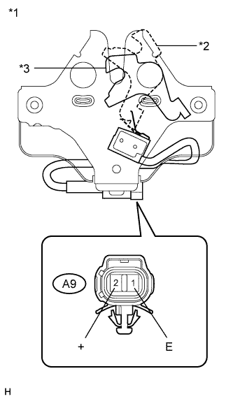
Text in Illustration *1 Component without harness connected
(Hood Lock Assembly (Engine Hood Courtesy Switch))
*2 Unlock *3 Lock Remove the hood lock assembly Click here.
-
Measure the resistance according to the value(s) in the table below.
Standard Resistance Tester Connection Switch Condition Specified Condition A9-1 (E) - A9-2 (+) Unlocked Below 1 Ω Locked 10 kΩ or higher
-
NG
REPLACE HOOD LOCK ASSEMBLY (ENGINE HOOD COURTESY SWITCH) Click here
OK
-
-
CHECK HARNESS AND CONNECTOR (ENGINE HOOD COURTESY SWITCH - BODY GROUND)
-
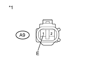
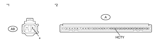
Text in Illustration *1 Front view of wire harness connector
(to Hood Lock Assembly (Engine Hood Courtesy Switch))
Measure the resistance according to the value(s) in the table below.
Standard Resistance Tester Connection Condition Specified Condition A9-1 (E) - Body ground Always Below 1 Ω
NG
REPAIR OR REPLACE HARNESS OR CONNECTOR
OK
-
-
CHECK HARNESS AND CONNECTOR (ENGINE HOOD COURTESY SWITCH - MAIN BODY ECU)
-
Reconnect the 2F instrument panel junction block assembly connector.
-
Measure the resistance according to the value(s) in the table below.
Standard Resistance Tester Connection Condition Specified Condition A9-2 (+) - A-20 (HCTY) Always Below 1 Ω A9-2 (+) - Body ground Always 10 kΩ or higher Text in Illustration *1 Front view of wire harness connector
(to Hood Lock Assembly (Engine Hood Courtesy Switch))
*2 Front view of wire harness connector
(to Main Body ECU (Multiplex Network Body ECU))
NG
REPAIR OR REPLACE HARNESS OR CONNECTOR
OK
REPLACE MAIN BODY ECU (MULTIPLEX NETWORK BODY ECU) Click here
-