ENGINE IMMOBILISER SYSTEM, Diagnostic DTC:B278A

| DTC Code | DTC Name |
|---|---|
| B278A | Short to GND in Immobiliser System Power Source Circuit |
DESCRIPTION
This DTC is stored when the power switch power source supply line is open or shorted.
| DTC No. | DTC Detection Condition | Trouble Area |
|---|---|---|
| B278A | Power switch power source supply line is open or shorted. |
|
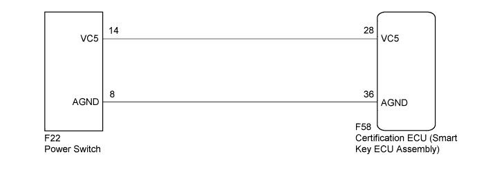
WIRING DIAGRAM
INSPECTION PROCEDURE
Note
If the certification ECU (smart key ECU assembly) is replaced, register the key.
PROCEDURE
-
CHECK DTC OUTPUT
-
Clear the DTCs Click here.
-
Recheck for DTCs Click here.
OK DTC B278A is not output.
NG 
CHECK HARNESS AND CONNECTOR (CERTIFICATION ECU - POWER SWITCH) Click here
OK 
USE SIMULATION METHOD TO CHECK Click here
-
-
CHECK HARNESS AND CONNECTOR (CERTIFICATION ECU - POWER SWITCH)
-
Disconnect the certification ECU (smart key ECU assembly) connector.
-
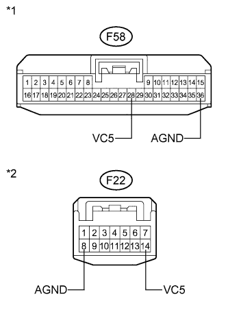
Text in Illustration *1 Front view of wire harness connector
(to Certification ECU (Smart Key ECU Assembly))
*2 Front view of wire harness connector
(to Power Switch)
Disconnect the power switch connector.
-
Measure the resistance according to the value(s) in the table below.
Standard Resistance Tester Connection Condition Specified Condition F58-28 (VC5) - F22-14 (VC5) Always Below 1 Ω F58-36 (AGND) - F22-8 (AGND) Always Below 1 Ω F58-28 (VC5) - Body ground Always 10 kΩ or higher F58-36 (AGND) - Body ground Always 10 kΩ or higher
NG 
REPAIR OR REPLACE HARNESS OR CONNECTOR
OK 
-
-
CHECK CERTIFICATION ECU (SMART KEY ECU ASSEMBLY)
-
Reconnect the certification ECU (smart key ECU assembly) connector.
-
Reconnect the power switch connector.
-
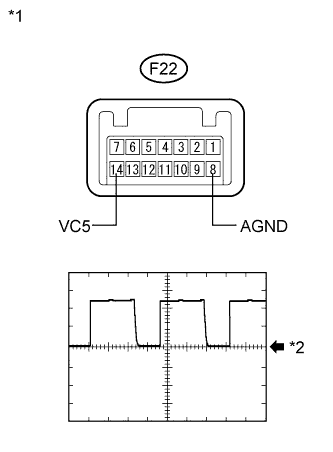
Text in Illustration *1 Component with harness connected
(Power Switch)
*2 GND Using an oscilloscope, check the waveform.
Waveform (Reference) Item Content Tester Connection F22-14 (VC5) - F22-8 (AGND) Tool Setting 2 V/DIV., 200 ms./DIV. Condition
-
Power switch off
-
Key not in cabin
-
Power switch pressed within 30 seconds
OK Waveform is output normally (see illustration) -
NG
REPLACE CERTIFICATION ECU (SMART KEY ECU ASSEMBLY)
OK
REPLACE POWER SWITCH Click here
-