ENTRY AND START SYSTEM (for Start Function), Diagnostic DTC:B2275

| DTC Code | DTC Name |
|---|---|
| B2275 | STSW Monitor Malfunction |
DESCRIPTION
This DTC is stored when a malfunction is detected in the starter circuit inside the power management control ECU.
| DTC No. | DTC Detection Condition | Trouble Area |
|---|---|---|
| B2275 | Power management control ECU internal HV activation request output circuit malfunction or external circuit malfunction. |
|
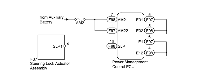
WIRING DIAGRAM
INSPECTION PROCEDURE
Note
-
When the power management control ECU is replaced with a new one and the cable from the negative (-) auxiliary battery terminal is connected, the power source mode becomes on (IG) mode. When the auxiliary battery is removed and reinstalled, the power source mode that was selected when the auxiliary battery was removed is restored.
-
Inspect the fuses for circuits related to this system before performing the following inspection procedure.
PROCEDURE
-
CHECK HARNESS AND CONNECTOR (AUXILIARY BATTERY - POWER MANAGEMENT CONTROL ECU)
-
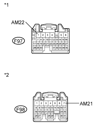
Text in Illustration *1 Front view of wire harness connector
(to Power Management Control ECU)
*2 Front view of wire harness connector
(to Power Management Control ECU)
Disconnect the F97 and F98 connectors from the power management control ECU.
-
Measure the voltage according to the value(s) in the table below.
Standard Voltage Tester Connection Condition Specified Condition F97-1 (AM22) - Body ground Always 9.5 to 16 V F98-7 (AM21) - Body ground Always 9.5 to 16 V
NG 
REPAIR OR REPLACE HARNESS OR CONNECTOR (AUXILIARY BATTERY - POWER MANAGEMENT CONTROL ECU)
OK 
-
-
CHECK HARNESS AND CONNECTOR (POWER MANAGEMENT CONTROL ECU - BODY GROUND)
-
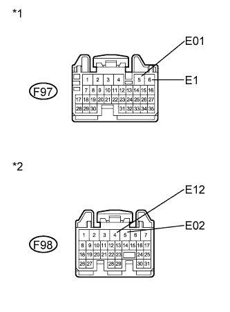
Text in Illustration *1 Front view of wire harness connector
(to Power Management Control ECU)
*2 Front view of wire harness connector
(to Power Management Control ECU)
Measure the resistance according to the value(s) in the table below.
Standard Resistance Tester Connection Condition Specified Condition F97-5 (E01) - Body ground Always Below 1 Ω F97-6 (E1) - Body ground Always Below 1 Ω F98-4 (E12) - Body ground Always Below 1 Ω F98-5 (E02) - Body ground Always Below 1 Ω
NG
REPAIR OR REPLACE HARNESS OR CONNECTOR
OK
-
-
CHECK FOR DTC
-
Clear the DTC Click here.
-
Turn the power switch on (IG).
-
After 25 seconds has elapsed, check if the DTC has been set again.
NG
GO TO OTHER FLOW CHART (DTC B2285) Click here
OK
-
-
CHECK STEERING LOCK ACTUATOR ASSEMBLY (STEERING LOCK ECU)
-
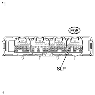
Text in Illustration *1 Component without harness connected
(Power Management Control ECU)
Measure the resistance according to the value(s) in the table below.
Standard Resistance Tester Connection Condition Specified Condition F98-16 (SLP) - Body ground Steering unlocked Below 1 Ω -
Proceed to next step based on inspection result.
Result Inspection Result Proceed to OK (for LHD) A OK (for RHD) B NG C
B
REPLACE POWER MANAGEMENT CONTROL ECU (for RHD) Click here
C
GO TO STEERING LOCK SYSTEM Click here
A 
REPLACE POWER MANAGEMENT CONTROL ECU (for LHD) Click here
-