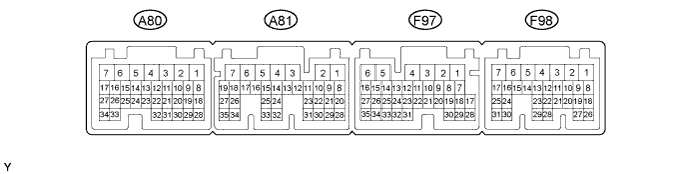
ENTRY AND START SYSTEM (for Start Function) TERMINALS OF ECU

-
CHECK POWER MANAGEMENT CONTROL ECU
-
Disconnect the A81, F97 and F98 connectors.
-
Measure the voltage and resistance according to the value(s) in the table below.
Tester Connection Wiring Color Terminal Description Condition Specified Condition A81-2 (IG2D) - Body ground B - Body ground IG2 relay operation signal Always 131 to 230 Ω A81-23 (STP) - Body ground R - Body ground Stop light switch signal Brake pedal depressed 11 to 14 V A81-23 (STP) - Body ground R - Body ground Stop light switch signal Brake pedal released Below 1 V F97-1 (AM22) - Body ground SB - Body ground +B power supply Always 11 to 14 V F98-7 (AM21) - Body ground R - Body ground +B power supply Always 11 to 14 V F98-16 (SLP) - Body ground G - Body ground Steering lock actuator assembly position signal Always 10 kΩ or higher F97-6 (E1) - Body ground BR - Body ground Ground Always Below 1 Ω F98-4 (E12) - Body ground W-B - Body ground Ground Power switch not pushed 10 kΩ or higher F98-6 (SLR+) - Body ground L - Body ground Steering lock motor signal Always 10 kΩ or higher F98-30 (CA3N) - Body ground W - Body ground CAN communication line Always 10 kΩ or higher F98-31 (CA3P) - Body ground V - Body ground CAN communication line Always 10 kΩ or higher F98-24 (CA1L) - Body ground R - Body ground CAN communication line Always 10 kΩ or higher F98-25 (CA1H) - Body ground LG - Body ground CAN communication line Always 10 kΩ or higher F98-17 (SSW2) - Body ground B - Body ground Power switch signal Power switch pushed Below 1 Ω F98-17 (SSW2) - Body ground B - Body ground Power switch signal Power switch not pushed 10 kΩ or higher F97-1 (SSW1) - Body ground LG - Body ground Power switch signal Power switch pushed Below 1 Ω F98-2 (IG1D) - Body ground G - Body ground IG1 relay operation signal Always 50.625 to 61.875 Ω F98-11 (LIN2) - Body ground V - Body ground LIN communication line Always 10 kΩ or higher If the result is not as specified, there may be a malfunction in the wire harness.
-
Reconnect the A81, F97 and F98 connectors.
-
Measure the voltage and check pulses according to the value(s) in the table below.
Tester Connection Wiring Color Terminal Description Condition Specified Condition A81-2 (IG2D) - F97-6 (E1) B - BR IG2 signal Power switch on (IG) Output voltage at terminal AM21 or AM22 is -2 V or more A81-2 (IG2D) - F97-6 (E1) B - BR IG2 signal Power switch on (ACC) Below 1 V F98-16 (SLP) - F97-6 (E1) G - BR Steering lock actuator assembly signal Steering lock released Pulse generation
(See waveform 1)
F98-16 (SLP) - F97-6 (E1) G - BR Steering lock actuator assembly signal Shift lever in P
Steering lock locked
Pulse generation
(See waveform 1)
F98-6 (SLR+) - F97-6 (E1) L - BR Steering motor signal Steering lock motor operating Below 1 V F98-6 (SLR+) - F97-6 (E1) L - BR Steering motor signal Steering lock motor not operating 11 to 14 V F97-9 (INDW) - F97-6 (E1) Y - BR Warning signal Brake pedal depressed, shift lever in P, power switch on (ACC, IG) 8 to 14 V F97-15 (P2) - F97-6 (E1) R - BR Shift lock signal Shift lever in P 8 to 14 V F97-15 (P2) - F97-6 (E1) R - BR Shift lock signal Shift lever not in P Below 1 V F98-17 (SSW2) - F97-6 (E1) B - BR Power switch signal Power switch not pushed Output voltage at terminal AM21 or AM22 is -2 V or more F98-17 (SSW2) - F97-6 (E1) B - BR Power switch signal Power switch pushed Below 1 V F97-1 (SSW1) - F97-6 (E1) LG - BR Power switch signal Power switch not pushed Output voltage at terminal AM21 or AM22 is -2 V or more F97-1 (SSW1) - F97-6 (E1) LG - BR Power switch signal Power switch pushed Below 1 V F98-1 (ACCD) - F97-6 (E1) GR - BR ACC signal Power switch on (ACC) 8 to 14 V F98-1 (ACCD) - F97-6 (E1) GR - BR ACC signal Power switch off Below 1 V F98-2 (IG1D) - F97-6 (E1) G - BR IG1 signal Power switch on (IG) 8 to 14 V F98-2 (IG1D) - F97-6 (E1) G - BR IG1 signal Power switch on (ACC) Below 1 V F97-8 (INDS) - F97-6 (E1) V - BR Vehicle condition signal Brake pedal depressed, shift lever in P 8 to 14 V F97-14 (SPDI) - F97-6 (E1) L - BR Vehicle speed signal Power switch on (IG), wheel rotated slowly Pulse generation
(See waveform 2)
F98-20 (IMO) - F97-6 (E1) LG - BR Immobiliser communication status Immobiliser communicating Pulse generation
(See waveform 3)
F98-21 (IMI) - F97-6 (E1) P - BR Immobiliser communication status Immobiliser communicating Pulse generation
(See waveform 3)
If the result is not as specified, the ECU may have a malfunction.
-
Using an oscilloscope, check the signal waveform of the ECU.
-
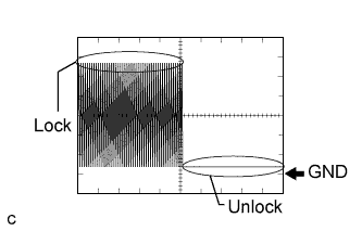
Waveform 1
Tester Connection F98-16 (SLP) - F97-6 (E1) Tool Setting 2 V/DIV., 100 ms./DIV. Vehicle Condition Steering lock/unlock -
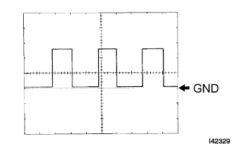
Waveform 2
Tester Connection F97-14 (SPDI) - F97-6 (E1) Tool Setting 5 V/DIV., 10 ms./DIV. Vehicle Condition Driving at approx. 20 km/h (12 mph) Tech Tips
The wavelength becomes shorter as the vehicle speed increases.
-
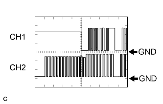
Waveform 3
Tester Connection CH1: F98-20 (IMO) - F97-6 (E1)
CH2: F98-21 (IMI) - F97-6 (E1)
Tool Setting 5 V/DIV., 200 ms./DIV. Vehicle Condition Power switch off → Power switch on (IG) → Power switch on (READY)
-
-
-
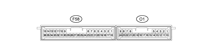
CHECK CERTIFICATION ECU (SMART KEY ECU ASSEMBLY)
-
Disconnect the F58 connector.
-
Measure the voltage and resistance according to the value(s) in the table below.
Tester Connection Wiring Color Terminal Description Condition Specified Condition F58-1 (+B) - Body ground LG - Body ground +B power supply Always 11 to 14 V F58-11 (SWIL) - Body ground G - Body ground Illumination signal Light control switch tail or head 8 to 14 V F58-15 (E)- Body ground W-B - Body ground Ground Always Below 1 Ω F58-16 (IG) - Body ground B - Body ground IG power supply Power switch on (IG) 11 to 14 V F58-29 (LIN) - Body ground V - Body ground LIN communication line Always 10 kΩ or higher If the result is not as specified, there may be a malfunction in the wire harness.
-
Reconnect the F58 connector.
-
Measure the voltage according to the value(s) in the table below.
Tester Connection Wiring Color Terminal Description Condition Specified Condition F58-11 (SWIL) - Body ground G - Body ground Illumination signal Light control switch tail or head 8 to 14 V If the result is not as specified, the ECU may have a malfunction.
-
-
CHECK STEERING LOCK ACTUATOR ASSEMBLY (STEERING LOCK ECU)

-
Disconnect the F37 connector.
-
Measure the voltage and resistance according to the value(s) in the table below.
Tester Connection Wiring Color Terminal Description Condition Specified Condition F37-1 (GND) - Body ground W-B - Body ground Ground Always Below 1 Ω F37-6 (IG2) - Body ground B - Body ground Ignition power supply Power switch on (IG) 11 to 14 V F37-6 (IG2) - Body ground B - Body ground Ignition power supply Power switch off Below 1 V F37-7 (B) - Body ground L - Body ground +B power supply Always 11 to 14 V
-
If the result is not as specified, there may be a malfunction in the wire harness.
-
-
Reconnect the F37 connector.
-
Measure the voltage according to the value(s) in the table below.
Tester Connection Wiring Color Terminal Description Condition Specified Condition F37-4 (SLP1) - F37-1 (GND) G - W-B Steering lock assembly position signal Steering locked 11 to 14 V F37-4 (SLP1) - F37-1 (GND) G - W-B Steering lock actuator position signal Steering released Below 1 V
-
If the result is not as specified, the ECU may have a malfunction.
-
-
-
CHECK ID CODE BOX (IMMOBILISER CODE ECU)

-
Disconnect the F45 connector.
-
Measure the resistance and voltage according to the value(s) in the table below.
Tester Connection Wiring Color Terminal Description Condition Specified Condition F45-1 (+B) - F45-8 (GND) B - W-B +B power supply Always 11 to 14 V F45-8 (GND) - Body ground W-B - Body ground Ground Always Below 1 Ω If the result is not as specified, there may be a malfunction in the wire harness.
-