ENTRY AND START SYSTEM (for Entry Function) Back Door Entry Lock and Unlock Functions do not Operate
DESCRIPTION
When the back door entry lock and unlock functions do not operate, one of the following may be malfunctioning: 1) power door lock control system; 2) outside electrical key oscillator (for rear side); 3) certification ECU (smart key ECU assembly), or 4) back door opener switch assembly.
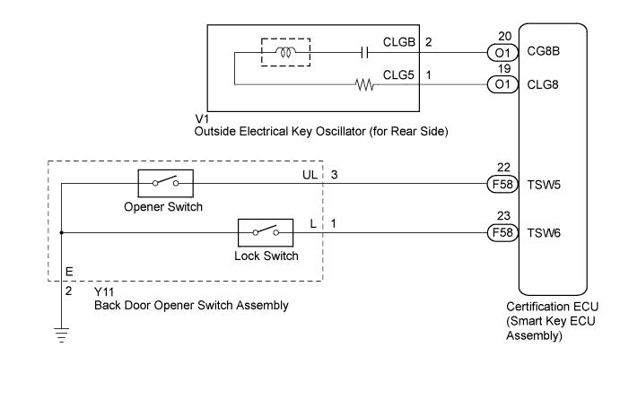
WIRING DIAGRAM
INSPECTION PROCEDURE
Note
-
The entry and start system (for entry function) uses a multiplex communication system (LIN communication system) and CAN communication system. Inspect the communication function by following How to Proceed with Troubleshooting Click here. Troubleshoot the entry and start system (for entry function) after confirming that the communication system is functioning properly.
-
Confirm that another key is not in the cabin.
PROCEDURE
-
CHECK POWER DOOR LOCK OPERATION
-
When the door control switch on the master switch assembly is operated, check that the doors unlock and lock according to switch operation Click here.
OK Door locks operate normally.
NG 
GO TO POWER DOOR LOCK CONTROL SYSTEM (Proceed to Problem Symptoms Table) Click here
OK 
-
-
READ VALUE USING INTELLIGENT TESTER (BACK DOOR OPENER SWITCH)
-
Connect the intelligent tester to the DLC3.
-
Turn the power switch on (IG).
-
Turn the intelligent tester on.
-
Enter the following menus: Body / Entry & Start / Data List.
-
Read the Data List according to the display on the intelligent tester.
Entry & Start (Certification ECU (Smart Key ECU Assembly)) Tester Display Measurement Item/Display Normal Condition Diagnostic Note Tr/B-Door Lock SW Back door opener switch assembly (lock switch) / ON or OFF ON: Back door opener switch assembly (lock switch) pushed
OFF: Back door opener switch assembly (lock switch) not pushed
- Tr/B-Door Unlock SW Back door opener switch assembly (opener switch) / ON or OFF ON: Back door opener switch assembly (opener switch) pushed
OFF: Back door opener switch assembly (opener switch) not pushed
- OK On the intelligent tester screen, the display changes between ON and OFF as shown in the chart above.
NG 
CHECK HARNESS AND CONNECTOR (BACK DOOR OPENER SWITCH - BODY GROUND) Click here
OK
-
-
CHECK WAVE ENVIRONMENT
-
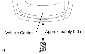
Bring the key near the outside electrical key oscillator (for rear side), and perform an entry back door open and entry lock functions check.
Note
If the key is brought within 0.2 m (0.656 ft.) of the rear bumper, communication is not possible.
Tech Tips
-
When pressing the lock switch and pressing the opener switch, hold the electrical key transmitter about 1 m (3.28 ft.) above the ground and about 0.3 m (0.984 ft.) away from the vehicle as shown in the illustration.
-
When the key is brought near the outside electrical key oscillator (for rear side), the possibility of wave interference decreases, and it can be determined if wave interference is causing the problem symptom.
-
If the operation is normal, the possibility of wave interference is high. Also, added vehicle components may cause wave interference. If installed, remove them and perform the operation.
OK Entry functions operate normally. -
NG
PERFORM KEY DIAGNOSTIC MODE INSPECTION Click here
OK 
AFFECTED BY WAVE INTERFERENCE
-
-
PERFORM KEY DIAGNOSTIC MODE INSPECTION
-
Diagnostic mode inspection (outside electrical key oscillator (for rear side))
-
Connect the intelligent tester to the DLC3.
-
Turn the power switch on (IG).
-
Turn the intelligent tester on.
-
Enter the following menus: Body / Entry & Start / Utility / Key Communication Check / Overhead + Back Door.
-
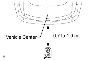
When the electrical key transmitter is in the position shown in the illustration, check that the wireless door lock buzzer sounds.
Tech Tips
-
Hold the electrical key transmitter at the same height as the rear bumper upper surface and align with the center of the rear of the vehicle (0.7 to 1.0 m (2.30 to 3.28 ft.)). Make sure that the direction of the key is as shown in the illustration.
-
If the buzzer sounds, it can be determined that the outside electrical key oscillator (for rear side) is operating normally.
OK Wireless door lock buzzer sounds. -
-
NG
CHECK HARNESS AND CONNECTOR (CERTIFICATION ECU - OUTSIDE ELECTRICAL KEY OSCILLATOR) Click here
OK
REPLACE CERTIFICATION ECU (SMART KEY ECU ASSEMBLY)
-
-
CHECK HARNESS AND CONNECTOR (CERTIFICATION ECU - OUTSIDE ELECTRICAL KEY OSCILLATOR)
-
Disconnect the certification ECU (smart key ECU assembly) connector.
-
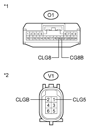
Text in Illustration *1 Front view of wire harness connector
(to Certification ECU (Smart Key ECU Assembly))
*2 Front view of wire harness connector
(to Outside Electrical Key Oscillator (for Rear Side))
Disconnect the outside electrical key oscillator (for rear side) connector.
-
Measure the resistance according to the value(s) in the table below.
Standard Resistance Tester Connection Condition Specified Condition O1-19 (CLG8) - V1-1 (CLG5) Always Below 1 Ω O1-20 (CG8B) - V1-2 (CLGB) Always Below 1 Ω O1-19 (CLG8) - Body ground Always 10 kΩ or higher O1-20 (CG8B) - Body ground Always 10 kΩ or higher V1-1 (CLG5) - Body ground Always 10 kΩ or higher V1-2 (CLGB) - Body ground Always 10 kΩ or higher
NG
REPAIR OR REPLACE HARNESS OR CONNECTOR
OK
-
-
INSPECT OUTSIDE ELECTRICAL KEY OSCILLATOR (for Rear Side)
-
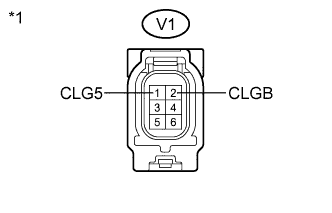
Text in Illustration *1 Component without harness connected
(Outside Electrical Key Oscillator (for Rear Side))
Measure the resistance according to the value(s) in the table below.
Standard Resistance Tester Connection Condition Specified Condition V1-1 (CLG5) - V1-2 (CLGB) Always Below 1 Ω
NG
REPLACE OUTSIDE ELECTRICAL KEY OSCILLATOR (for Rear Side) Click here
OK
REPLACE CERTIFICATION ECU (SMART KEY ECU ASSEMBLY)
-
-
CHECK HARNESS AND CONNECTOR (BACK DOOR OPENER SWITCH - BODY GROUND)
-
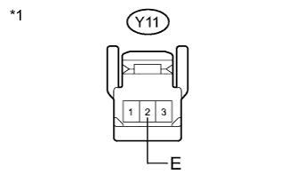
Text in Illustration *1 Front view of wire harness connector
(to Back Door Opener Switch Assembly))
Disconnect the back door opener switch assembly connector.
-
Measure the resistance according to the value(s) in the table below.
Standard Resistance Tester Connection Condition Specified Condition Y11-2 (E) - Body ground Always Below 1 Ω
NG
REPAIR OR REPLACE HARNESS OR CONNECTOR
OK
REPLACE BACK DOOR OPENER SWITCH ASSEMBLY Click here
-