ENTRY AND START SYSTEM (for Entry Function) Back Door Entry Unlock Function does not Operate
DESCRIPTION
If the entry back door open function does not operate but the back door entry lock function operates, the communication between the vehicle and key is normal. As a faulty part, the back door open switch circuit (from the back door opener switch assembly (opener switch) to the certification ECU (smart key ECU assembly)) is suspected.
WIRING DIAGRAM
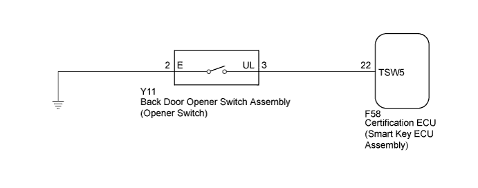
INSPECTION PROCEDURE
Note
-
The entry and start system (for entry function) uses a multiplex communication system (LIN communication system) and CAN communication system. Inspect the communication function by following How to Proceed with Troubleshooting Click here. Troubleshoot the entry and start system (for entry function) after confirming that the communication system is functioning properly.
-
Confirm that another key is not in the cabin.
PROCEDURE
-
READ VALUE USING INTELLIGENT TESTER (ENTRY BACK DOOR OPEN FUNCTION)
-
Connect the intelligent tester to the DLC3.
-
Turn the power switch on (IG).
-
Turn the intelligent tester on.
-
Enter the following menus: Body / Entry & Start / Data List.
-
Read the Data List according to the display on the intelligent tester.
Entry & Start (Certification ECU (Smart Key ECU Assembly)) Tester Display Measurement Item/Range Normal Condition Diagnostic Note B-Dr Opening Operation Back door opening Operation / Long, Twice, OFF Customization status displayed - Result Result Proceed to Customize setting is LONG or TWICE. A Customize setting is OFF. B
B 
PERFORM CUSTOMIZE SETTING (Proceed to Customize Parameters) Click here
A 
-
-
CHECK POWER DOOR LOCK OPERATION
-
When the door control switch on the master switch assembly is operated, check that the doors unlock and lock according to switch operation Click here.
OK Door locks operate normally.
NG
GO TO POWER DOOR LOCK CONTROL SYSTEM (Proceed to Problem Symptoms Table) Click here
OK
-
-
READ VALUE USING INTELLIGENT TESTER (BACK DOOR OPENER SWITCH)
-
Connect the intelligent tester to the DLC3.
-
Turn the power switch on (IG).
-
Turn the intelligent tester on.
-
Enter the following menus: Body / Entry & Start / Data List.
-
Read the Data List according to the display on the intelligent tester.
Entry & Start (Certification ECU (Smart Key ECU Assembly)) Tester Display Measurement Item/Range Normal Condition Diagnostic Note Tr/B-Door Unlock SW Back door opener switch assembly (opener switch) / ON or OFF ON: Back door opener switch assembly (opener switch) pushed
OFF: Back door opener switch assembly (opener switch) not pushed
- OK On the intelligent tester screen, the display changes between ON and OFF as shown in the chart above.
NG 
INSPECT BACK DOOR OPENER SWITCH ASSEMBLY Click here
OK 
REPLACE CERTIFICATION ECU (SMART KEY ECU ASSEMBLY)
-
-
INSPECT BACK DOOR OPENER SWITCH ASSEMBLY
-
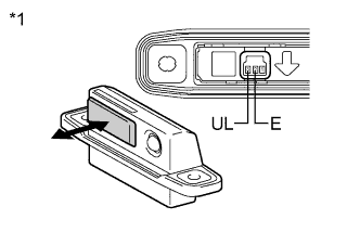
Text in Illustration *1 Component without harness connected
(Back Door Opener Switch Assembly)
Remove the back door opener switch assembly Click here.
-
Measure the resistance according to the value(s) in the table below.
Standard Resistance Tester Connection Switch Position Specified Condition 2 (E) - 3 (UL) Back door opener switch assembly (opener switch) not pushed (OFF) 10 kΩ or higher 2 (E) - 3 (UL) Back door opener switch assembly (opener switch) pushed (ON) Below 1 Ω
NG
REPLACE BACK DOOR OPENER SWITCH ASSEMBLY Click here
OK
-
-
CHECK HARNESS AND CONNECTOR (CERTIFICATION ECU - BACK DOOR OPENER SWITCH)
-
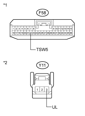
Text in Illustration *1 Front view of wire harness connector
(to Certification ECU (Smart Key ECU Assembly))
*2 Front view of wire harness connector
(to Back Door Opener Switch Assembly)
Disconnect the certification ECU (smart key ECU Assembly) connector.
-
Measure the resistance according to the value(s) in the table below.
Standard Resistance Tester Connection Condition Specified Condition F58-22 (TSW5) - Y11-3 (UL) Always Below 1 Ω F58-22 (TSW5) - Body ground Always 10 kΩ or higher Y11-3 (UL) - Body ground Always 10 kΩ or higher
NG
REPAIR OR REPLACE HARNESS OR CONNECTOR
OK
REPLACE CERTIFICATION ECU (SMART KEY ECU ASSEMBLY)
-