ENTRY AND START SYSTEM (for Start Function), Diagnostic DTC:U0293

| DTC Code | DTC Name |
|---|---|
| U0293 | Lost Communication with HV ECU |
DESCRIPTION
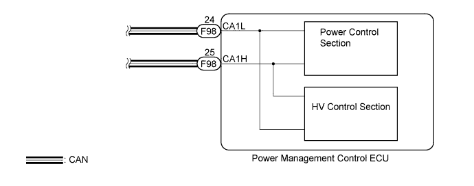
This DTC is stored when the power management control ECU detects a CAN communication error inside the power management control ECU (power control section - HV control section).
| DTC No. | DTC Detection Condition | Trouble Area |
|---|---|---|
| U0293 | CAN communication signal error inside the power management control ECU (power control section - HV control section). |
|
WIRING DIAGRAM
INSPECTION PROCEDURE
Note
When the power management control ECU is replaced with a new one and the cable from the negative (-) auxiliary battery terminal is connected, the power source mode becomes on (IG) mode. When the auxiliary battery is removed and reinstalled, the power source mode that was selected when the auxiliary battery was removed is restored.
PROCEDURE
-
CHECK HARNESS AND CONNECTOR (AUXILIARY BATTERY - POWER MANAGEMENT CONTROL ECU)
-
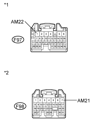
Text in Illustration *1 Front view of wire harness connector
(to Power Management Control ECU)
*2 Front view of wire harness connector
(to Power Management Control ECU)
Disconnect the F97 and F98 connectors from the power management control ECU.
-
Measure the voltage according to the value(s) in the table below.
Standard Voltage Tester Connection Condition Specified Condition F97-1 (AM22) - Body ground Always 9.5 to 16 V F98-7 (AM21) - Body ground Always 9.5 to 16 V
NG 
REPAIR OR REPLACE HARNESS OR CONNECTOR (AUXILIARY BATTERY - POWER MANAGEMENT CONTROL ECU)
OK 
-
-
CHECK HARNESS AND CONNECTOR (POWER MANAGEMENT CONTROL ECU - BODY GROUND)
-
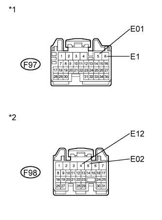
Text in Illustration *1 Front view of wire harness connector
(to Power Management Control ECU)
*2 Front view of wire harness connector
(to Power Management Control ECU)
Measure the resistance according to the value(s) in the table below.
Standard Resistance Tester Connection Condition Specified Condition F97-5 (E01) - Body ground Always Below 1 Ω F97-6 (E1) - Body ground Always Below 1 Ω F98-4 (E12) - Body ground Always Below 1 Ω F98-5 (E02) - Body ground Always Below 1 Ω
NG
REPAIR OR REPLACE HARNESS OR CONNECTOR (POWER MANAGEMENT CONTROL ECU - BODY GROUND)
OK
-
-
CHECK FOR DTC
-
Clear the DTC Click here.
-
Check for DTC again.
Result Result Proceed to DTC U0293 is not output A DTC U0293 is output (for LHD) B DTC U0293 is output (for RHD) C
B
REPLACE POWER MANAGEMENT CONTROL ECU (for LHD) Click here
C
REPLACE POWER MANAGEMENT CONTROL ECU (for RHD) Click here
A 
USE SIMULATION METHOD TO CHECK Click here
-