ENTRY AND START SYSTEM (for Entry Function) All Door Entry Lock/Unlock Functions and Wireless Functions do not Operate
DESCRIPTION
When the entry door lock and unlock functions and wireless door lock and unlock functions do not operate, radio wave interference, or a malfunction in the key or signal circuit between the door control receiver assembly and certification ECU (smart key ECU assembly) is suspected. The signal circuit is shared by the entry function and wireless door lock function.
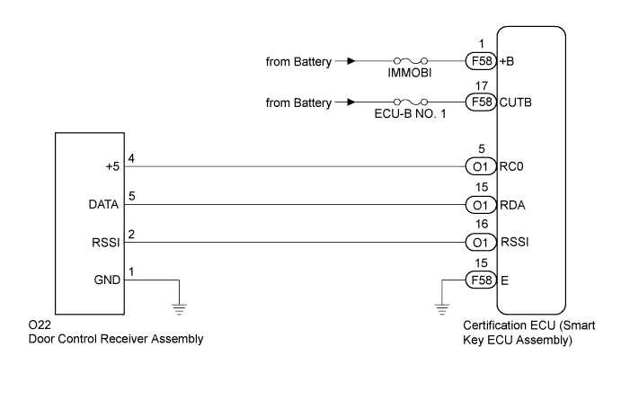
WIRING DIAGRAM
INSPECTION PROCEDURE
Note
-
The entry and start system (for entry function) uses a multiplex communication system (LIN communication system) and CAN communication system. Inspect the communication function by following How to Proceed with Troubleshooting Click here. Troubleshoot the entry and start system (for entry function) after confirming that the communication system is functioning properly.
-
Before performing the inspection, check that DTC B1242 (wireless door lock control) is not output Click here.
-
Confirm that another key is not in the cabin.
-
When only the key (for card type) does not operate the entry lock/unlock functions for all doors, it can be suspected that the key (for card type) is malfunctioning or its battery is depleted. Refer to Problem Symptoms Table Click here.
PROCEDURE
-
CHECK POWER DOOR LOCK OPERATION
-
When the door control switch on the master switch assembly is operated, check that the doors unlock and lock according to switch operation Click here.
OK Door locks operate normally.
NG 
GO TO POWER DOOR LOCK CONTROL SYSTEM (Proceed to Problem Symptoms Table) Click here
OK 
-
-
CHECK ELECTRICAL KEY TRANSMITTER
-
Check if another registered key is available.
Result Result Proceed to Another registered key is not available. A Another registered key is available. B
B 
CHECK ELECTRICAL KEY TRANSMITTER (OPERATION) Click here
A
-
-
REGISTER ELECTRICAL KEY TRANSMITTER
-
Register a new key.
NEXT
-
-
CHECK ELECTRICAL KEY TRANSMITTER (OPERATION)
-
Using the key registered in the previous step or another registered key, check that the entry function operates normally Click here.
OK Entry function operates normally.
NG
CHECK WAVE ENVIRONMENT Click here
OK
-
-
CHECK ELECTRICAL KEY TRANSMITTER (LED)
-
Check that the transmitter LED illuminates each time when the switch is pushed 3 times.
Result Result Proceed to Transmitter LED does not illuminate at all when switch is pushed 3 times. A Transmitter LED illuminates each time when switch is pushed 3 times. B Transmitter LED does not illuminate the second or third time. C Tech Tips
If the transmitter LED does not illuminate the second or third time, replace the transmitter battery as it is depleted.
B
REPLACE ELECTRICAL KEY TRANSMITTER
C
REPLACE TRANSMITTER BATTERY Click here
A
-
-
INSPECT TRANSMITTER BATTERY (VOLTAGE)
-
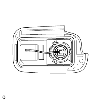
Remove the battery from the key that does not operate. Attach a lead wire (0.6 mm (0.0236 in.) or less in diameter including wire sheath) with tape or equivalent to the negative (-) terminal Click here.
Note
Do not wrap the wire around the terminal, wedge it between the terminals, or solder it. A terminal may be deformed or damaged, and the battery will not be able to be installed correctly.
-
Carefully pull the lead wire out from the position shown in the illustration and install the previously removed transmitter battery.
-
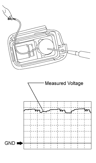
Using an oscilloscope, check the transmitter battery voltage waveform.
Tech Tips
When measuring the battery voltage, while operating the lock switch of a door outside handle assembly, bring the key within the entry operating range to perform the measurement. For the entry operating range, refer to System Description Click here.
Standard Voltage Item Content Tester Connection Battery positive (+) - Battery negative (-) Tool Setting 0.5 V/DIV., 100 ms/DIV. Condition Power switch off, all doors closed and lock switch pushed Specified Condition 2.2 to 3.2 V (Refer to the waveform)
NG
REPLACE TRANSMITTER BATTERY Click here
OK 
REPLACE ELECTRICAL KEY TRANSMITTER
-
-
CHECK WAVE ENVIRONMENT
-
Bring the key near the door control receiver, and check the wireless function.
Tech Tips
-
When the key is brought near the door control receiver, the possibility of wave interference decreases, and it can be determined if wave interference is causing the problem symptom.
-
If the inspection result indicates that the problem only occurs in certain locations or times of day, the possibility of wave interference is high. Also, added vehicle components may cause wave interference. If installed, remove them and perform the operation check.
OK Wireless function operates normally. -
NG
CHECK POWER SOURCE Click here
OK
AFFECTED BY WAVE INTERFERENCE
-
-
CHECK POWER SOURCE
-
Check if functions other than the entry function operate when the power switch is off.
Result Result Proceed to Other functions do not operate. A Other functions operate. B Tech Tips
Perform this check using functions that do not require the power switch to be on (ACC or IG) in order to operate.
B
GO TO ENTRY AND START SYSTEM (for Start Function) (Proceed to How to Proceed with Troubleshooting) Click here
A
-
-
INSPECT FUSES (IMMOBI, ECU-B NO. 1)
-
Remove the IMMOBI and ECU-B NO. 1 fuses from the engine room relay block and junction block.
-
Measure the resistance according to the value(s) in the table below.
Standard Resistance Tester Connection Condition Specified Condition IMMOBI fuse Always Below 1 Ω ECU-B NO. 1 fuse Always Below 1 Ω
NG
REPLACE FUSE (IMMOBI, ECU-B NO. 1)
OK
-
-
CHECK HARNESS AND CONNECTOR (CERTIFICATION ECU - BATTERY AND BODY GROUND)
-
Install the IMMOBI and ECU-B NO. 1 fuses to the engine room relay block and junction block.
-
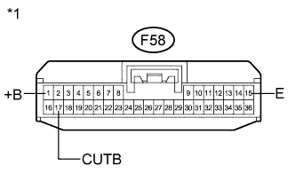
Text in Illustration *1 Front view of wire harness connector
(to Certification ECU (Smart Key ECU Assembly))
Disconnect the certification ECU (smart key ECU assembly) connector.
-
Measure the voltage and resistance according to the value(s) in the table below.
Standard Voltage Tester Connection Condition Specified Condition F58-1 (+B) - Body ground Except power switch on (READY) 11 to 14 V F58-1 (+B) - Body ground Power switch on (READY) 11 to 15.5 V F58-17 (CUTB) - Body ground Except power switch on (READY) 11 to 14 V F58-17 (CUTB) - Body ground Power switch on (READY) 11 to 15.5 V Standard Resistance Tester Connection Condition Specified Condition F58-15 (E) - Body ground Always Below 1 Ω
NG
REPAIR OR REPLACE HARNESS OR CONNECTOR
OK
-
-
CHECK HARNESS AND CONNECTOR (CERTIFICATION ECU - DOOR CONTROL RECEIVER)
-
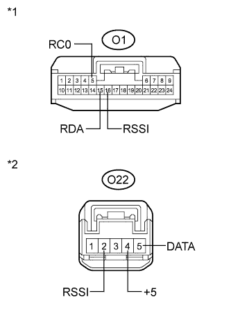
Text in Illustration *1 Front view of wire harness connector
(to Certification ECU (Smart Key ECU Assembly))
*2 Front view of wire harness connector
(to Door Control Receiver Assembly)
Disconnect the door control receiver assembly connector.
-
Measure the resistance according to the value(s) in the table below.
Standard Resistance Tester Connection Condition Specified Condition O1-5 (RC0) - O22-4 (+5) Always Below 1 Ω O1-15 (RDA) - O22-5 (DATA) Always Below 1 Ω O1-16 (RSSI) - O22-2 (RSSI) Always Below 1 Ω O1-5 (RC0) - Body ground Always 10 kΩ or higher O1-15 (RDA) - Body ground Always 10 kΩ or higher O1-16 (RSSI) - Body ground Always 10 kΩ or higher O22-4 (+5) - Body ground Always 10 kΩ or higher O22-5 (DATA) - Body ground Always 10 kΩ or higher O22-2 (RSSI) - Body ground Always 10 kΩ or higher
NG
REPAIR OR REPLACE HARNESS OR CONNECTOR
OK
-
-
CHECK HARNESS AND CONNECTOR (DOOR CONTROL RECEIVER - BODY GROUND)
-
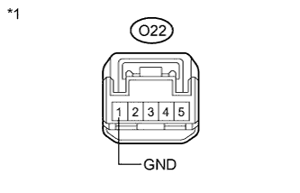
Text in Illustration *1 Front view of wire harness connector
(to Door Control Receiver Assembly)
Measure the resistance according to the value(s) in the table below.
Standard Resistance Tester Connection Condition Specified Condition O22-1 (GND) - Body ground Always Below 1 Ω
NG
REPAIR OR REPLACE HARNESS OR CONNECTOR
OK
-
-
INSPECT DOOR CONTROL RECEIVER ASSEMBLY (POWER SOURCE)
-
Reconnect the certification ECU (smart key ECU assembly) connector.
-
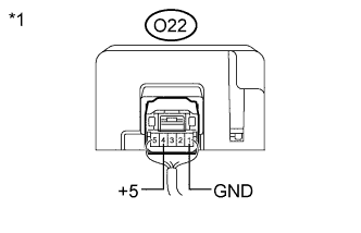
Text in Illustration *1 Component with harness connected
(Door Control Receiver Assembly)
Reconnect the door control receiver assembly connector.
-
Measure the voltage according to the value(s) in the table below.
Standard Voltage Tester Connection Condition Specified Condition O22-4 (+5) - O22-1 (GND)
-
Power switch off
-
Lock or unlock switch on key not pushed
Below 1 V O22-4 (+5) - O22-1 (GND)
-
Power switch off
-
Lock or unlock switch on key pushed
4.5 to 5.5 V -
NG
REPLACE CERTIFICATION ECU (SMART KEY ECU ASSEMBLY)
OK
-
-
INSPECT DOOR CONTROL RECEIVER ASSEMBLY (DOOR CONTROL RECEIVER SIGNAL OUTPUT)
-
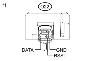
Text in Illustration *1 Component with harness connected
(Door Control Receiver Assembly)
Measure the voltage according to the value(s) in the table below.
Standard Voltage Tester Connection Condition Specified Condition O22-2 (RSSI) - O22-1 (GND)
-
Power switch off
-
All doors locked
-
Lock or unlock switch on key not pushed
11 to 14 V O22-2 (RSSI) - O22-1 (GND)
-
Power switch off
-
All doors locked
-
Lock or unlock switch on key pushed
Below 2 V O22-5 (DATA) - O22-1 (GND) Power switch off Pulse between 11 to 14 V occurs regularly -
NG
REPLACE DOOR CONTROL RECEIVER ASSEMBLY Click here
OK
REPLACE CERTIFICATION ECU (SMART KEY ECU ASSEMBLY)
-