ENTRY AND START SYSTEM (for Entry Function) Driver Side Door Entry Lock Function does not Operate
DESCRIPTION
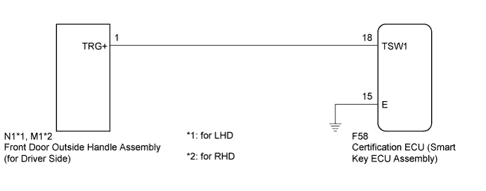
If the driver door entry unlock function operates normally, but its entry lock function does not, this means that the request code from the driver door is being output normally. In this case, a malfunction in the lock sensor circuit (from the certification ECU (smart key ECU assembly) to the front door outside handle assembly (lock sensor)) is suspected.
WIRING DIAGRAM
INSPECTION PROCEDURE
Note
-
The entry and start system (for entry function) uses a multiplex communication system (LIN communication system) and CAN communication system. Inspect the communication function by following How to Proceed with Troubleshooting Click here. Troubleshoot the entry and start system (for entry function) after confirming that the communication system is functioning properly.
-
Confirm that another key is not in the cabin.
PROCEDURE
-
CHECK POWER DOOR LOCK OPERATION
-
When the door control switch on the master switch assembly is operated, check that the doors unlock and lock according to switch operation Click here.
OK Door locks operate normally.
NG 
GO TO POWER DOOR LOCK CONTROL SYSTEM (Proceed to Problem Symptoms Table) Click here
OK 
-
-
READ VALUE USING INTELLIGENT TESTER (DOOR LOCK POSITION SWITCH)
-
Connect the intelligent tester to the DLC3.
-
Turn the power switch on (IG).
-
Turn the intelligent tester on.
-
Enter the following menus: Body / Main Body / Data List.
-
Read the Data List according to the display on the intelligent tester.
Main Body (Main Body ECU (Multiplex Network Body ECU)) Tester Display Measurement Item/Range Normal Condition Diagnostic Note FR Door Lock Pos*1 Front right side lock position switch signal/LOCK or UNLOCK LOCK: Front right side door locked
UNLOCK: Front right side door unlocked
- FL Door Lock Pos*2 Front left side door lock position switch signal/LOCK or UNLOCK LOCK: Front left side door locked
UNLOCK: Front left side door unlocked
-
-
*1: for RHD
-
*2: for LHD
OK On the intelligent tester screen, the display changes between LOCK and UNLOCK as shown in the chart above. -
NG
GO TO LIGHTING SYSTEM (Proceed to Door Unlock Detection Switch Circuit) Click here
OK
-
-
READ VALUE USING INTELLIGENT TESTER (DOOR OUTSIDE HANDLE)
-
Enter the following menus: Body / Entry & Start / Data List.
-
Read the Data List according to the display on the intelligent tester.
Entry & Start (Certification ECU (Smart Key ECU Assembly)) Tester Display Measurement Item/Range Normal Condition Diagnostic Note D-Door Trigger SW Driver side door lock switch / ON or OFF ON: Entry lock sensor touched
OFF: Entry lock sensor not touched
- OK On the intelligent tester screen, the display changes between ON and OFF as shown in the chart above.
NG 
CHECK HARNESS AND CONNECTOR (CERTIFICATION ECU - FRONT DOOR OUTSIDE HANDLE) Click here
OK 
REPLACE CERTIFICATION ECU (SMART KEY ECU ASSEMBLY)
-
-
CHECK HARNESS AND CONNECTOR (CERTIFICATION ECU - FRONT DOOR OUTSIDE HANDLE)
-
Disconnect the certification ECU (smart key ECU assembly) connector.
-
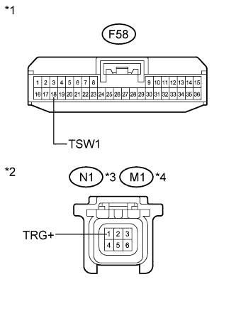
Text in Illustration *1 Front view of wire harness connector
(to Certification ECU (Smart Key ECU Assembly))
*2 Front view of wire harness connector
(to Front Door Outside Handle Assembly (for Driver Side))
*3 for LHD *4 for RHD Disconnect the front door outside handle assembly (for driver side) connector.
-
Measure the resistance according to the value(s) in the table below.
Standard Resistance for LHD Tester Connection Condition Specified Condition F58-18 (TSW1) - N1-1 (TRG+) Always Below 1 Ω F58-18 (TSW1) - Body ground Always 10 kΩ or higher N1-1 (TRG+) - Body ground Always 10 kΩ or higher for RHD Tester Connection Condition Specified Condition F58-18 (TSW1) - M1-1 (TRG+) Always Below 1 Ω F58-18 (TSW1) - Body ground Always 10 kΩ or higher M1-1 (TRG+) - Body ground Always 10 kΩ or higher
NG
REPAIR OR REPLACE HARNESS OR CONNECTOR
OK
-
-
INSPECT CERTIFICATION ECU (SMART KEY ECU ASSEMBLY) (LOCK SENSOR SIGNAL INPUT)
-
Reconnect the certification ECU (smart key ECU assembly) connector.
-
Reconnect the front door outside handle assembly (for driver side) connector.
-
Measure the voltage and check for pulses according to the value(s) in the table below.
Standard Tester Connection Condition Specified Condition F58-18 (TSW1) - F58-15 (E)
-
Power switch off
-
All doors closed
-
Lock sensor (for driver side) not touched
Pulse generation F58-18 (TSW1) - F58-15 (E)
-
Power switch off
-
All doors closed
-
Lock sensor (for driver side) touched
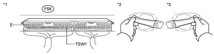
Below 2 V Text in Illustration *1 Component with harness connected
(Certification ECU (Smart Key ECU Assembly))
*2 for LHD *3 for RHD - - -
NG
REPLACE FRONT DOOR OUTSIDE HANDLE ASSEMBLY (for Driver Side) Click here
OK
REPLACE CERTIFICATION ECU (SMART KEY ECU ASSEMBLY)
-