ENTRY AND START SYSTEM (for Entry Function) TERMINALS OF ECU

-
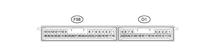
CHECK CERTIFICATION ECU (SMART KEY ECU ASSEMBLY)
-
Disconnect the F58 certification ECU (smart key ECU assembly) connector.
-
Measure the voltage and resistance according to the value(s) in the table below.
Tech Tips
Measure the values on the wire harness side with connector disconnected.
Tester Connection Wiring Color Terminal Description Condition Specified Condition F58-1 (+B) - Body ground LG - Body ground +B power supply Always 11 to 14 V F58-15 (E) - Body ground W-B - Body ground Ground Always Below 1 Ω F58-17 (CUTB) - Body ground L - Body ground Dark current cut fuse pin input signal Always 11 to 14 V If the result is not as specified, there may be a malfunction in the wire harness.
-
Reconnect the F58 certification ECU (smart key ECU assembly) connector.
-
Measure the voltage and check for pulses according to the value(s) in the table below.
Tester Connection Wiring Color Terminal Description Condition Specified Condition F58-3 (CLG1) - F58-15 (E) P - W-B Door electrical key oscillator (for driver side) sensor signal
-
Power switch off
-
All doors closed
-
Key not in cabin
No pulse generation F58-3 (CLG1) - F58-15 (E) P - W-B Door electrical key oscillator (for driver side) sensor signal
-
Power switch off
-
All doors closed
-
Key not in cabin
-
All doors locked by wireless lock function
Pulse generation F58-4 (CG1B) - F58-15 (E) Y - W-B Door electrical key oscillator (for driver side) sensor signal
-
Power switch off
-
All doors closed
-
Key not in cabin
No pulse generation F58-4 (CG1B) - F58-15 (E) Y - W-B Door electrical key oscillator (for driver side) sensor signal
-
Power switch off
-
All doors closed
-
Key not in cabin
-
All doors locked by wireless lock function
Pulse generation F58-5 (CLG2) - F58-15 (E) P - W-B Door electrical key oscillator (for front passenger side) sensor signal
-
Power switch off
-
All doors closed
-
Key not in cabin
No pulse generation F58-5 (CLG2) - F58-15 (E) P - W-B Door electrical key oscillator (for front passenger side) sensor signal
-
Power switch off
-
All doors closed
-
Key not in cabin
-
All doors locked by wireless lock function
Pulse generation F58-6 (CG2B) - F58-15 (E) Y - W-B Door electrical key oscillator (for front passenger side) sensor signal
-
Power switch off
-
All doors closed
-
Key not in cabin
No pulse generation F58-6 (CG2B) - F58-15 (E) Y - W-B Door electrical key oscillator (for front passenger side) sensor signal
-
Power switch off
-
All doors closed
-
Key not in cabin
-
All doors locked by wireless lock function
Pulse generation F58-7 (CLG5) - F58-15 (E) LG - W-B Indoor electrical key oscillator (for front floor) sensor signal
-
Power switch off
-
All doors closed
-
Key not in cabin
-
Door outside handle assembly (lock sensor) not touched
No pulse generation F58-7 (CLG5) - F58-15 (E) LG - W-B Indoor electrical key oscillator (for front floor) sensor signal
-
Power switch off
-
All doors closed
-
Key not in cabin
-
Door outside handle assembly (lock sensor) touched
Pulse generation F58-8 (CG5B) - F58-15 (E) W - W-B Indoor electrical key oscillator (for front floor) sensor signal
-
Power switch off
-
All doors closed
-
Key not in cabin
-
Door outside handle assembly (lock sensor) not touched
No pulse generation F58-8 (CG5B) - F58-15 (E) W - W-B Indoor electrical key oscillator (for front floor) sensor signal
-
Power switch off
-
All doors closed
-
Key not in cabin
-
Door outside handle assembly (lock sensor) touched
Pulse generation F58-16 (IG) - Body ground B - Body ground IG power supply Power switch off Below 1 V F58-16 (IG) - Body ground B - Body ground IG power supply Power switch on (IG) 11 to 14 V F58-18 (TSW1) - F58-15 (E) V - W-B Lock sensor (for driver side) detection signal
-
Power switch off
-
All doors closed
-
Lock sensor (for driver side) not touched
Pulse generation F58-18 (TSW1) - F58-15 (E) V - W-B Lock sensor (for driver side) detection signal
-
Power switch off
-
All doors closed
-
Lock sensor (for driver side) touched
Below 2 V F58-19 (TSW2) - F58-15 (E) BR - W-B Lock sensor (for front passenger side) detection signal
-
Power switch off
-
All doors closed
-
Lock sensor (for front passenger side) not touched
Pulse generation F58-19 (TSW2) - F58-15 (E) BR - W-B Lock sensor (for front passenger side) detection signal
-
Power switch off
-
All doors closed
-
Lock sensor (for front passenger side) touched
Below 2 V F58-20 (SEN1) - F58-15 (E) R - W-B Touch sensor (for driver side) detection signal
-
Power switch off
-
All doors closed
-
Key not in detection area
-
Touch sensor (for driver side) not touched
Pulse generation F58-20 (SEN1) - F58-15 (E) R - W-B Touch sensor (for driver side) detection signal
-
Power switch off
-
All doors closed
-
Key not in detection area
-
Touch sensor (for driver side) touched
Below 2 V F58-21 (SEN2) - F58-15 (E) W - W-B Touch sensor (for front passenger side) detection signal
-
Power switch off
-
All doors closed
-
Key not in detection area
-
Touch sensor (for front passenger side) not touched
Pulse generation F58-21 (SEN2) - F58-15 (E) W - W-B Touch sensor (for front passenger side) detection signal
-
Power switch off
-
All doors closed
-
Key not in detection area
-
Touch sensor (for front passenger side) touched
Below 2 V F58-22 (TSW5) - F58-15 (E) L - W-B Back door opener switch assembly (opener switch) signal Back door opener switch assembly (opener switch) not pushed Pulse generation F58-22 (TSW5) - F58-15 (E) L - W-B Back door opener switch assembly (opener switch) signal Back door opener switch assembly (opener switch) pushed Below 1 V F58-23 (TSW6) - F58-15 (E) P - W-B Back door opener switch assembly (lock switch) signal Back door opener switch assembly (lock switch) not pushed Pulse generation F58-23 (TSW6) - F58-15 (E) P - W-B Back door opener switch assembly (lock switch) signal Back door opener switch assembly (lock switch) pushed Below 1 V F58-24 (CLG6) - F58-15 (E) V - W-B Indoor electrical key oscillator (for center floor) sensor signal
-
Power switch off
-
All doors closed
-
Key not in cabin
-
Door outside handle assembly (lock sensor) not touched
No pulse generation F58-24 (CLG6) - F58-15 (E) V - W-B Indoor electrical key oscillator (for center floor) sensor signal
-
Power switch off
-
All doors closed
-
Key not in cabin
-
Door outside handle assembly (lock sensor) touched
Pulse generation F58-25 (CG6B) - F58-15 (E) G - W-B Indoor electrical key oscillator (for center floor) sensor signal
-
Power switch off
-
All doors closed
-
Key not in cabin
-
Door outside handle assembly (lock sensor) not touched
No pulse generation F58-25 (CG6B) - F58-15 (E) G - W-B Indoor electrical key oscillator (for center floor) sensor signal
-
Power switch off
-
All doors closed
-
Key not in cabin
-
Door outside handle assembly (lock sensor) touched
Pulse generation F58-26 (CLG7) - F58-15 (E) P - W-B Indoor electrical key oscillator (for rear floor) sensor signal
-
Power switch off
-
All doors closed
-
Key not in cabin
-
Door outside handle assembly (lock sensor) not touched
No pulse generation F58-26 (CLG7) - F58-15 (E) P - W-B Indoor electrical key oscillator (for rear floor) sensor signal
-
Power switch off
-
All doors closed
-
Key not in cabin
-
Door outside handle assembly (lock sensor) touched
Pulse generation F58-27 (CG7B) - F58-15 (E) V - W-B Indoor electrical key oscillator (for rear floor) sensor signal
-
Power switch off
-
All doors closed
-
Key not in cabin
-
Door outside handle assembly (lock sensor) not touched
No pulse generation F58-27 (CG7B) - F58-15 (E) V - W-B Indoor electrical key oscillator (for rear floor) sensor signal
-
Power switch off
-
All doors closed
-
Key not in cabin
-
Door outside handle assembly (lock sensor) touched
Pulse generation F58-32 (POS1) - F58-15 (E) Y - W-B Lock or unlock sensor (for driver side) output signal Power switch off 9 to 14 V F58-32 (POS1) - F58-15 (E) Y - W-B Lock or unlock sensor (for driver side) output signal Power switch on (IG) Below 2 V F58-33 (POS2) - F58-15 (E) B - W-B Lock or unlock sensor (for front passenger side) output signal Power switch off 9 to 14 V F58-33 (POS2) - F58-15 (E) B - W-B Lock or unlock sensor (for front passenger side) output signal Power switch on (IG) Below 2 V O1-5 (RC0) - F58-15 (E) L - W-B Door control receiver power source
-
Power switch off
-
Lock or unlock switch on key not pushed
Below 1 V O1-5 (RC0) - F58-15 (E) L - W-B Door control receiver power source
-
Power switch off
-
Lock or unlock switch on key pushed
4.5 to 5.5 V O1-15 (RDA) - F58-15 (E) Y - W-B Door control receiver data input signal Power switch off Pulse between 11 to 14 V occurs regularly O1-16 (RSSI) - F58-15 (E) R - W-B Door control receiver electric wave existence signal
-
Power switch off
-
All doors locked
-
Lock or unlock switch on key not pushed
11 to 14 V O1-16 (RSSI) - F58-15 (E) R - W-B Door control receiver electric wave existence signal
-
Power switch off
-
All doors locked
-
Lock or unlock switch on key pushed
Below 2 V O1-19 (CLG8) - F58-15 (E) P - W-B Outside electrical key oscillator (for rear side) sensor signal
-
Power switch off
-
All doors closed
-
Back door opener switch assembly off
No pulse generation O1-19 (CLG8) - F58-15 (E) P - W-B Outside electrical key oscillator (for rear side) sensor signal
-
Power switch off
-
All doors closed
-
Back door opener switch assembly on
Pulse generation O1-20 (CG8B) - F58-15 (E) V - W-B Outside electrical key oscillator (for rear side) sensor signal
-
Power switch off
-
All doors closed
-
Back door opener switch assembly off
No pulse generation O1-20 (CG8B) - F58-15 (E) V - W-B Outside electrical key oscillator (for rear side) sensor signal
-
Power switch off
-
All doors closed
-
Back door opener switch assembly on
Pulse generation If the result is not as specified, the certification ECU (smart key ECU assembly) may have a malfunction.
-
-
-
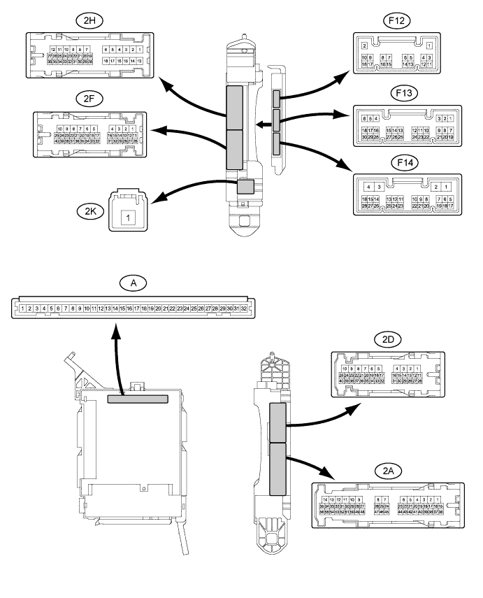
CHECK INSTRUMENT PANEL JUNCTION BLOCK ASSEMBLY, MAIN BODY ECU (MULTIPLEX NETWORK BODY ECU)
-
Disconnect the 2F, F14 and 2D junction block connectors.
-
Disconnect the A main body ECU (multiplex network body ECU) connector.
-
Measure the voltage and resistance according to the value(s) in the table below.
Tech Tips
Measure the values on the wire harness side with the connector disconnected.
Tester Connection Wiring Color Terminal Description Condition Specified Condition 2D-6 (GND1) - Body ground BR - Body ground Ground Always Below 1 Ω 2F-40 (BECU) - Body ground G - Body ground Battery power supply Except power switch on (READY) 11 to 14 V 2F-40 (BECU) - Body ground G - Body ground Battery power supply Power switch on (READY) 11 to 15.5 V F14-3 (GND2) - Body ground W-B - Body ground Ground Always Below 1 Ω A-29 (ACC) - Body ground - ACC power supply Power switch on (ACC) 11 to 14 V A-29 (ACC) - Body ground - ACC power supply Power switch on (ACC) Below 1 V A-31 (ALTB) - Body ground - Battery power supply Except power switch on (READY) 11 to 14 V A-31 (ALTB) - Body ground - Battery power supply Power switch on (READY) 11 to 15.5 V A-32 (IG) - Body ground - IG power supply Power switch on (IG) 11 to 14 V A-32 (IG) - Body ground - IG switch power supply Power switch off Below 1 V If the result is not as specified, there may be a malfunction in the wire harness or instrument panel junction block assembly.
-
Reconnect the 2F, F14 and 2D junction block connectors.
-
Reconnect the A main body ECU (multiplex network body ECU) connector.
-
Measure the voltage according to the value(s) in the table below.
Tester Connection Wiring Color Terminal Description Condition Specified Condition 2D-1 (ACT-) - Body ground R - Body ground Door lock motor unlock drive output (except driver side) Multiplex network master switch (door control switch) or driver side door key cylinder off Below 1 V 2D-1 (ACT-) - Body ground R - Body ground Door lock motor unlock drive output (except driver side) Multiplex network master switch (door control switch) or driver side door key cylinder unlock 11 to 14 V 2D-3 (ACT+) - Body ground L - Body ground Door lock motor lock drive output (all doors) Multiplex network master switch (door control switch) or driver side door key cylinder off Below 1 V 2D-3 (ACT+) - Body ground L - Body ground Door lock motor lock drive output (all doors) Multiplex network master switch (door control switch) or driver side door key cylinder lock 11 to 14 V 2D-7 (ACTD) - Body ground R - Body ground Driver side door lock motor unlock drive output Multiplex network master switch (door control switch) or driver side door key cylinder off Below 1 V 2D-7 (ACTD) - Body ground R - Body ground Driver side door lock motor unlock drive output Multiplex network master switch (door control switch) or driver side door key cylinder unlock 11 to 14 V 2D-26 (FRCY) - Body ground L - Body ground Front door courtesy switch RH input Front door RH open Below 1 V 2D-26 (FRCY) - Body ground L - Body ground Front door courtesy switch RH input Front door RH closed 11 to 14 V 2H-26 (FLCY) - Body ground B - Body ground Front door courtesy switch LH input Front door LH open Below 1 V 2H-26 (FLCY) - Body ground B - Body ground Front door courtesy switch LH input Front door LH closed 11 to 14 V 2H-27 (LSWL) - Body ground Y - Body ground Rear door LH lock position switch input Rear door LH unlock Below 1 V 2H-27 (LSWL) - Body ground Y - Body ground Rear door LH lock position switch input Power switch off, all doors closed and rear door LH locked 11 to 14 V F12-3 (LCTY) - Body ground L - Body ground Rear door LH courtesy light switch input Rear door LH open Below 1 V F12-3 (LCTY) - Body ground L - Body ground Rear door LH courtesy light switch input Rear door LH closed 11 to 14 V F13-6 (RCTY) - Body ground GR - Body ground Rear door RH courtesy light switch input Rear door RH open Below 1 V F13-6 (RCTY) - Body ground GR - Body ground Rear door RH courtesy light switch input Rear door RH closed 11 to 14 V F13-7 (LSFL) - Body ground P - Body ground Front door lock position switch LH input Front door LH unlock Below 1 V F13-7 (LSFL) - Body ground P - Body ground Front door lock position switch LH input Power switch off, all doors closed and front door LH locked 11 to 14 V F13-9 (L1) - Body ground LG - Body ground Front passenger side door control switch input Front passenger side door control switch lock Below 1 V F13-9 (L1) - Body ground LG - Body ground Front passenger side door control switch input Front passenger side door control switch off 11 to 14 V F13-10 (UL1) - Body ground L - Body ground Front passenger side door control switch input Front passenger side door control switch unlock Below 1 V F13-10 (UL1) - Body ground L - Body ground Front passenger side door control switch input Front passenger side door control switch off 11 to 14 V F13-11 (L2) - Body ground BR - Body ground Driver side door key-linked lock input Driver side door key cylinder turned to lock Below 1 V F13-11 (L2) - Body ground BR - Body ground Driver side door key-linked lock input Driver side door key cylinder off 11 to 14 V F13-18 (LSFR) - Body ground SB - Body ground Front door lock position switch RH input Front door RH unlock Below 1 V F13-18 (LSFR) - Body ground SB - Body ground Front door lock position switch RH input Power switch off, all doors closed and front door RH locked 11 to 14 V F13-19 (BCTY) - Body ground* R - Body ground Back door courtesy light switch input Back door open Below 1 V F13-19 (BCTY) - Body ground* R - Body ground Back door courtesy light switch input Back door closed 11 to 14 V F13-24 (UL3) - Body ground GR - Body ground Driver side door key-linked unlock input Driver side door key cylinder turned to unlock Below 1 V F13-24 (UL3) - Body ground GR - Body ground Driver side door key-linked unlock input Driver side door key cylinder off 11 to 14 V F14-2 (LSWR) - Body ground B - Body ground Rear door RH lock position switch input Rear door RH unlock Below 1 V F14-2 (LSWR) - Body ground B - Body ground Rear door RH lock position switch input Power switch off, all doors closed and rear door RH locked 11 to 14 V *: w/o Power Back Door System
If the result is not as specified, the main body ECU (multiplex network body ECU) or instrument panel junction block assembly may have a malfunction.
-
-
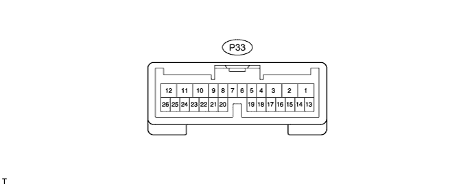
CHECK POWER BACK DOOR ECU (POWER BACK DOOR MOTOR UNIT) (w/ Power Back Door System)
-
Disconnect the P33 power back door ECU (power back door motor unit) connector.
-
Measure the voltage and resistance according to the value(s) in the table below.
Tech Tips
Measure the values on the wire harness side with the connector disconnected.
Tester Connection Wiring Color Terminal Description Condition Specified Condition P33-12 (B) - Body ground Y - Body ground Battery power supply Except power switch on (READY) 11 to 14 V P33-12 (B) - Body ground Y - Body ground Battery power supply Power switch on (READY) 11 to 15.5 V P33-10 (ECUB) - Body ground BR - Body ground Battery power supply Except power switch on (READY) 11 to 14 V P33-10 (ECUB) - Body ground BR - Body ground Battery power supply Power switch on (READY) 11 to 15.5 V P33-8 (IG) - Body ground SB - Body ground IG power supply Power switch on (IG) 11 to 14 V P33-8 (IG) - Body ground SB - Body ground IG power supply Power switch off Below 1 V P33-11 (GND) - Body ground W-B - Body ground Ground Always Below 1 Ω If the result is not as specified, there may be a malfunction in the wire harness.
-
Reconnect the P33 power back door ECU (power back door motor unit) connector.
-
Initialize the power back door ECU (power back door motor unit) Click here.
-
Measure the voltage according to the value(s) in the table below.
Tester Connection Wiring Color Terminal Description Condition Specified Condition P33-20 (FUL) - Body ground P - Body ground Back door courtesy switch circuit Back door closed 11 to 14 V P33-20 (FUL) - Body ground P - Body ground Back door courtesy switch circuit Back door open Below 1 V If the result is not as specified, the power back door ECU (power back door motor unit) may have a malfunction.
-
-
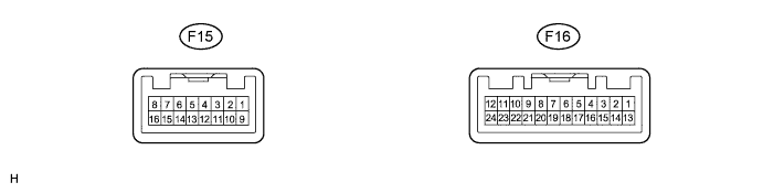
COMBINATION METER ASSEMBLY
-
Disconnect the F15 and F16 combination meter assembly connectors.
-
Measure the resistance according to the value(s) in the table below.
Tech Tips
Measure the values on the wire harness side with the connector disconnected.
Tester Connection Wiring Color Terminal Description Condition Specified Condition F15-16 (E2) - Body ground W-B - Body ground Ground Always Below 1 Ω F16-1 (IG+) - Body ground GR - Body ground IG power supply Power switch off Below 1 V F16-1 (IG+) - Body ground GR - Body ground IG power supply Power switch on (IG) 11 to 14 V F16-13 (B) - Body ground SB - Body ground Battery power supply Except power switch on (READY) 11 to 14 V F16-13 (B) - Body ground SB - Body ground Battery power supply Power switch on (READY) 11 to 15.5 V If the result is not as specified, there may be a malfunction in the wire harness.
-