FRONT DOOR LOCK INSTALLATION

-
INSTALL FRONT DOOR LOCK ASSEMBLY (w/o Double Locking System)
Note
-
When reusing the removed front door lock assembly, replace the door lock wiring harness seal on the connector with a new one.
-
Do not allow grease or dust to adhere to the door lock wiring harness seal surface of the connector.
-
Reusing the door lock wiring harness seal or using a damaged door lock wiring harness seal may cause water intrusion. This may result in a malfunction of the front door lock assembly.
-
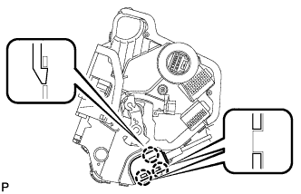
Install the front door inside locking cable assembly.
-
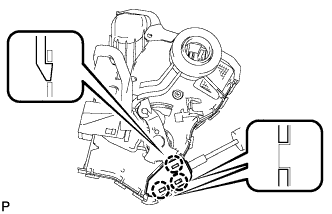
Engage the 3 claws.
-
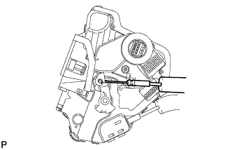
Install the front door lock remote control cable assembly.
-
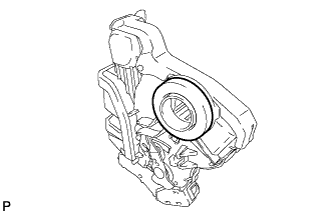
Apply MP grease to the sliding parts of the front door lock assembly.
-
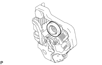
Install a new door lock wiring harness seal to the front door lock assembly.
-
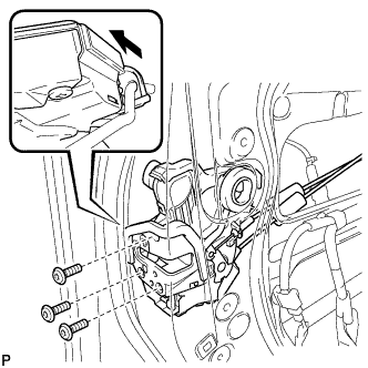
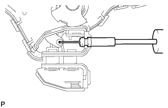
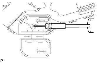
Insert the front door lock open rod to the front door lock assembly.
-
Make sure that the front door lock open rod is securely connected to the front door lock assembly.
-
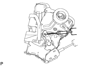
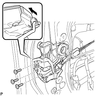
Using a T30 "TORX" socket wrench, install the front door lock assembly with the 3 screws.
- Torque:
- 5.0 N*m { 51 kgf*cm, 44 in.*lbf }
-
-
INSTALL FRONT DOOR LOCK ASSEMBLY (w/ Double Locking System)
Note
-
When reusing the removed front door lock assembly, replace the door lock wiring harness seal on the connector with a new one.
-
Do not allow grease or dust to adhere to the door lock wiring harness seal surface of the connector.
-
Reusing the door lock wiring harness seal or using a damaged door lock wiring harness seal may cause water intrusion. This may result in a malfunction of the front door lock assembly.
-
Install the front door inside locking cable assembly.
-
Engage the 3 claws.
-
Install the front door lock remote control cable assembly.
-
Apply MP grease to the sliding parts of the front door lock assembly.
-
Install a new door lock wiring harness seal to the front door lock assembly.
-
Insert the front door lock open rod to the front door lock assembly.
-
Make sure that the front door lock open rod is securely connected to the front door lock assembly.
-
Using a T30 "TORX" socket wrench, install the front door lock assembly with the 3 screws.
- Torque:
- 5.0 N*m { 51 kgf*cm, 44 in.*lbf }
-
-
INSTALL FRONT DOOR OUTSIDE HANDLE COVER WITH LOCK CYLINDER ASSEMBLY
-
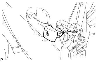
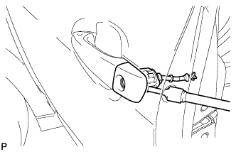
Install the front door outside handle cover with lock cylinder assembly.
Tech Tips
Make sure that the front door lock cylinder rod is inserted into the front door lock assembly.
-
Using a T30 "TORX" socket wrench, install the front door lock cylinder with the screw.
- Torque:
- 4.0 N*m { 41 kgf*cm, 35 in.*lbf }
-
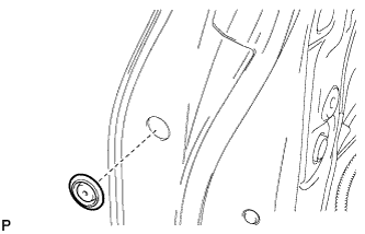
Install the hole plug.
-
-
INSTALL FRONT DOOR REAR LOWER FRAME SUB-ASSEMBLY
-
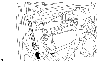
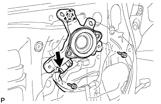
Install the front door rear lower frame sub-assembly with the bolt as shown in the illustration.
-
-
INSTALL FRONT DOOR GLASS RUN
-
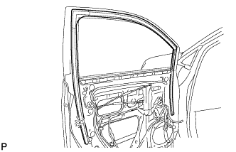
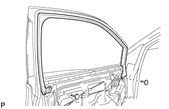
Install the front door glass run.
-
-
INSTALL FRONT DOOR GLASS SUB-ASSEMBLY
-
Connect the cable to the negative (-) battery terminal.
-
Connect the power window regulator master switch assembly and move the front door glass subassembly so that the door glass bolts can be seen.
-
w/ Navigation System for HDD:
Note
After the power switch is turned off, the display and navigation module display (HDD navigation system) records various types of memory and settings. As a result, after turning the power switch off, make sure to wait for the time specified in the following table before disconnecting the cable from the negative (-) battery terminal.
Waiting Time before Disconnecting Cable from Negative (-) Battery Terminal Specification Waiting Time w/o Telematics transceiver 60 sec. w/ Telematics transceiver 120 sec.
-
-
Disconnect the cable from the negative (-) battery terminal and power window regulator master switch assembly.
CAUTION:
Wait at least 90 seconds after disconnecting the cable from the negative (-) battery terminal to disable the SRS system Click here.
-
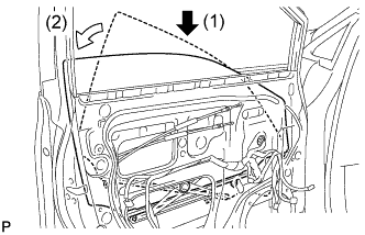
Insert the front door glass sub-assembly into the front door panel along the front door glass run as indicated by the arrows in the order shown in the illustration.
-
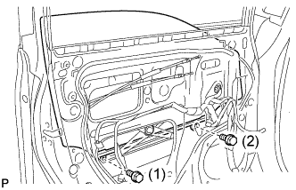
Install the front door glass sub-assembly with the 2 bolts.
- Torque:
- 5.5 N*m { 56 kgf*cm, 49 in.*lbf }
Tech Tips
Tighten the bolts in the order shown in the illustration.
-
-
INSTALL FRONT DOOR SERVICE HOLE COVER
-
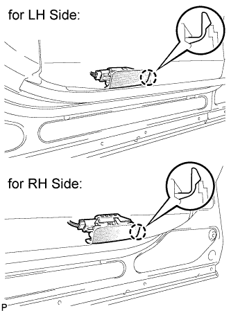
Apply butyl tape to the front door panel.
-
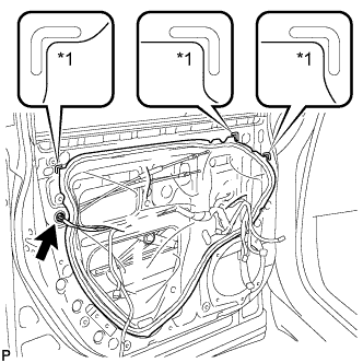
Text in Illustration *1 Reference Point Pass the front door lock remote control cable assembly and front door inside locking cable assembly through a new front door service hole cover.
-
Attach the front door service hole cover according to the reference points on the front door panel.
Note
Securely install the front door service hole cover preventing wrinkles and air bubbles.
-
Connect the connector.
-
-
INSTALL NO. 1 FRONT DOOR TRIM BRACKET
-
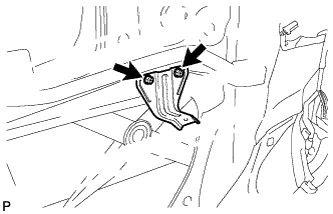
Install the 2 bolts and No. 1 front door trim bracket.
-
-
INSTALL OUTER MIRROR CONTROL ECU ASSEMBLY
-
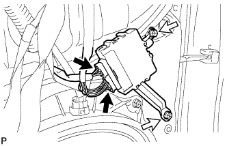
Install the outer mirror control ECU assembly with the 2 screws.
-
Connect each connector.
-
-
INSTALL FRONT NO. 3 SPEAKER ASSEMBLY
-
Engage the clip and temporarily install the front No. 3 speaker assembly.
-
Install the front No. 3 speaker assembly with the 2 screws.
-
Connect the connector.
-
-
INSTALL DOOR FRAME GARNISH
-
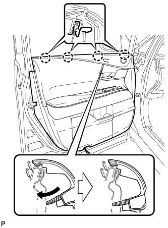
Install the door frame garnish with the 2 clips.
-
-
INSTALL FRONT DOOR INNER GLASS WEATHERSTRIP
-
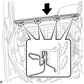
Engage the 4 claws and install the front door inner glass weatherstrip as shown in the illustration.
-
-
INSTALL FRONT DOOR TRIM BOARD SUB-ASSEMBLY
-
Install a new front door trim board retainer (green).
-
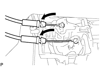
Connect the front door lock remote control cable assembly and front door inside locking cable assembly.
-
Connect each connector.
-
Engage the front door trim board sub-assembly with the 4 claws of the front door inner glass weatherstrip as shown in the illustration.
-
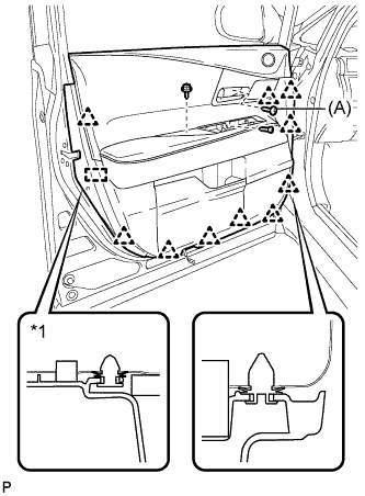
Text in Illustration *1 Front Door Trim Board Retainer Engage the 10 clips, front door trim board retainer and install the front door trim board sub-assembly.
-
Install the 3 screws.
- Torque:
- (A)
- 3.5 N*m { 36 kgf*cm, 31 in.*lbf }
-
-
INSTALL NO. 1 FRONT DOOR STIFFENER CUSHION
-
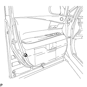
Install the No. 1 front door stiffener cushion with the screw.
-
-
INSTALL COURTESY LIGHT ASSEMBLY
-
Connect the connector.
-
Engage the claw to install the courtesy light assembly.
-
-
INSTALL DOOR ARMREST COVER
-
Install the door armrest cover.
-
-
INSTALL POWER WINDOW REGULATOR MASTER SWITCH ASSEMBLY WITH FRONT DOOR ARMREST BASE PANEL (for Driver Side)
-
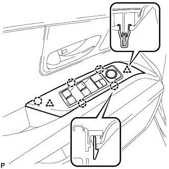
Connect the connector.
-
Engage the 2 clips and 5 claws, and install the power window regulator master switch assembly with front door armrest base panel.
-
-
INSTALL POWER WINDOW REGULATOR SWITCH ASSEMBLY WITH FRONT DOOR ARMREST BASE PANEL (for Front Passenger Side)
-
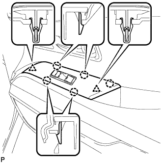
Connect the connector.
-
Engage the 2 clips and 5 claws, and install the power window regulator switch assembly with front door armrest base panel.
-
-
INSTALL FRONT DOOR INSIDE HANDLE BEZEL PLUG
-
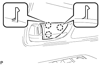
Engage the 3 claws and install the front door inside handle bezel plug.
-
-
CONNECT CABLE TO NEGATIVE BATTERY TERMINAL
Note
When disconnecting the cable, some systems need to be initialized after the cable is reconnected Click here.
-
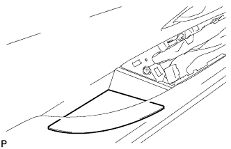
INSTALL REAR DECK FLOOR BOX
-

Install the rear deck floor box with the 3 clips.
-
-
INITIALIZE POWER WINDOW CONTROL SYSTEM