POWER DOOR LOCK CONTROL SYSTEM Only Back Door cannot be Opened
DESCRIPTION
-
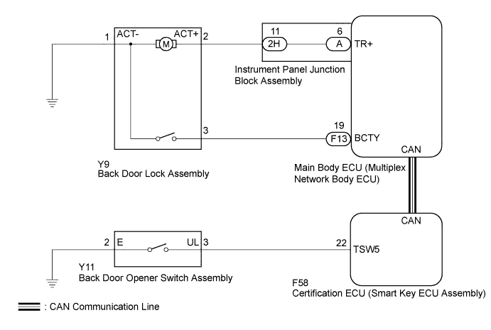
The main body ECU (multiplex network body ECU) detects the condition of the back door opener switch assembly.
-
The certification ECU (smart key ECU assembly) receives signals from the back door opener switch assembly and activates the back door lock motor according to the signals.
WIRING DIAGRAM
INSPECTION PROCEDURE
Note
The power door lock control system uses the CAN communication system. First, confirm that there is no malfunction in the CAN communication system. Refer to the How to Proceed with Troubleshooting procedure Click here.
PROCEDURE
-
CHECK POWER DOOR LOCK OPERATION (BASIC FUNCTION)
-
Check the power door lock basic function Click here.
OK The power door lock basic functions operate normally.
NG 
GO TO PROBLEM SYMPTOMS TABLE Click here
OK 
-
-
READ VALUE USING INTELLIGENT TESTER (DOOR LOCK STATUS)
-
Connect the intelligent tester to the DLC3.
-
Turn the power switch on (IG).
-
Turn the intelligent tester on.
-
Enter the following menus: Body / Main Body / Data List.
-
Read the Data List according to the display on the intelligent tester.
Main Body (Main Body ECU (Multiplex Network Body ECU)) Tester Display Measurement Item/Range Normal Condition Diagnostic Note Back Door Open Back door lock/Permit or Prohibit Permit: Back door unlocked
Prohibit: Back door locked
- OK The intelligent tester indicates Permit or Prohibit according to the door lock operation shown in the table.
NG
REPLACE MAIN BODY ECU (MULTIPLEX NETWORK BODY ECU) Click here
OK
-
-
PERFORM ACTIVE TEST USING INTELLIGENT TESTER
-
Connect the intelligent tester to the DLC3.
-
Turn the power switch on (IG).
-
Turn the intelligent tester on.
-
Enter the following menus: Body / Main Body / Active Test.
-
Perform the Active Test according to the display on the intelligent tester.
Main Body (Main Body ECU (Multiplex Network Body ECU)) Tester Display Test Part Control Range Diagnostic Note Trunk and Back-Door Open Operate back door lock motor ON or OFF - OK The back door lock assembly unlatches when ON is selected.
NG 
INSPECT BACK DOOR LOCK ASSEMBLY Click here
OK
-
-
READ VALUE USING INTELLIGENT TESTER
-
Connect the intelligent tester to the DLC3.
-
Turn the power switch on (IG).
-
Turn the intelligent tester on.
-
Enter the following menus: Body / Entry&Start / Data List.
-
Read the Data List according to the display on the intelligent tester.
Entry&Start (Certification ECU (Smart Key ECU Assembly)) Tester Display Measurement Item/Range Normal Condition Diagnostic Note Tr/B-Door Unlock SW Back door opener switch signal/ON or OFF ON: Back door opener switch pushed
OFF: Back door opener switch not pushed
- OK The intelligent tester indicates ON or OFF according to the switch operation shown in the table.
NG
INSPECT BACK DOOR OPENER SWITCH ASSEMBLY Click here
OK
-
-
REPLACE MAIN BODY ECU (MULTIPLEX NETWORK BODY ECU)
-
Replace the main body ECU (multiplex network body ECU) Click here.
NEXT
-
-
CHECK BACK DOOR OPEN OPERATION
-
Check that the back door can be opened.
OK The back door can be opened normally.
NG
REPLACE CERTIFICATION ECU (SMART KEY ECU ASSEMBLY)
OK 
END (MAIN BODY ECU (MULTIPLEX NETWORK BODY ECU) WAS DEFECTIVE)
-
-
INSPECT BACK DOOR LOCK ASSEMBLY
-
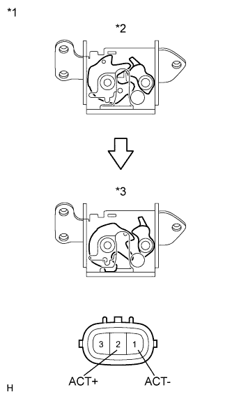
Text in Illustration *1 Component without harness connected
(Back Door Lock Assembly)
*2 Lock *3 Unlock Remove the back door lock assembly Click here.
-
Check the operation of the door lock motor.
-
Move the door lock to the lock position.
-
Apply auxiliary battery voltage to the door lock motor and check the operation of the door lock motor.
Connection Result Auxiliary battery positive (+) → Terminal 2 (ACT+)
Auxiliary battery negative (-) → Terminal 1 (ACT-)
Unlocks
-
-
Check the operation of the door courtesy switch.
-
Measure the resistance according to the value(s) in the table below.
Standard Resistance Tester Connection Condition Specified Condition 1 (ACT-) - 3 Locked 10 kΩ or higher 1 (ACT-) - 3 Unlocked Below 1 Ω
-
NG
REPLACE BACK DOOR LOCK ASSEMBLY Click here
OK
-
-
CHECK HARNESS AND CONNECTOR (BACK DOOR LOCK ASSEMBLY - MAIN BODY ECU)
-
Disconnect the F13 main body ECU connector.
-
Disconnect the 2H instrument panel junction block connector.
-
Measure the resistance according to the value(s) in the table below.
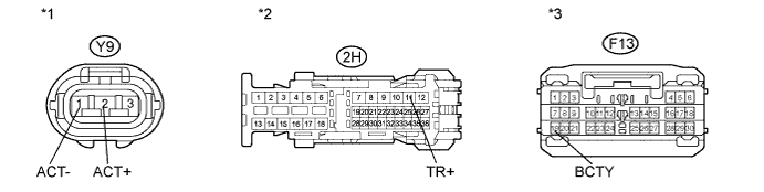
Standard Resistance Tester Connection Condition Specified Condition Y9-2 (ACT+) - 2H-11 (TR+) Always Below 1 Ω Y9-2 (ACT+) - Body ground Always 10 kΩ or higher Y9-3 - F13-19 (BCTY) Always Below 1 Ω Y9-3 - Body ground Always 10 kΩ or higher Y9-1 (ACT-) - Body ground Always Below 1 Ω Text in Illustration *1 Front view of wire harness connector
(to Back Door Lock Assembly)
*2 Front view of wire harness connector
(to Instrument Panel Junction Block Assembly)
*3 Front view of wire harness connector
(to Main Body ECU (Multiplex Network Body ECU))
- -
NG
REPAIR OR REPLACE HARNESS OR CONNECTOR
OK
-
-
REPLACE INSTRUMENT PANEL JUNCTION BLOCK ASSEMBLY
-
Replace the instrument panel junction block assembly.
NEXT
-
-
CHECK BACK DOOR OPEN OPERATION
-
Check that the back door can be opened.
OK The back door can be opened normally.
NG
REPLACE MAIN BODY ECU (MULTIPLEX NETWORK BODY ECU) Click here
OK
END (INSTRUMENT PANEL JUNCTION BLOCK ASSEMBLY WAS DEFECTIVE)
-
-
INSPECT BACK DOOR OPENER SWITCH ASSEMBLY
-
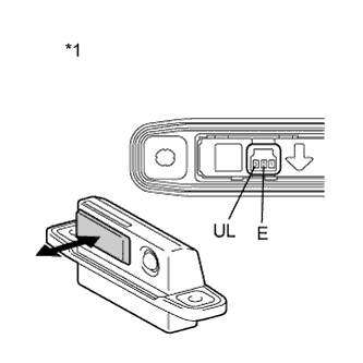
Text in Illustration *1 Component without harness connected
(Back Door Opener Switch Assembly)
Remove the back door opener switch Click here.
-
Check the operation of the opener switch.
-
Measure the resistance according to the value(s) in the table below.
Standard Resistance Tester Connection Switch Condition Specified Condition 2 (E) - 3 (UL) Back door opener switch not pushed 10 kΩ or higher 2 (E) - 3 (UL) Back door opener switch pushed Below 1 Ω
-
NG
REPLACE BACK DOOR OPENER SWITCH ASSEMBLY Click here
OK
-
-
CHECK HARNESS AND CONNECTOR (BACK DOOR OPENER SWITCH ASSEMBLY - CERTIFICATION ECU)
-
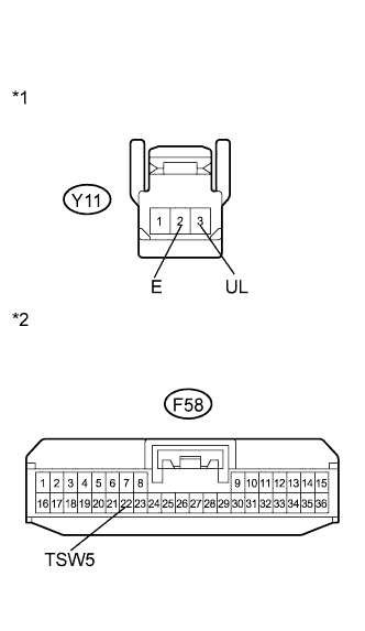
Text in Illustration *1 Front view of wire harness connector
(to Back Door Opener Switch Assembly)
*2 Front view of wire harness connector
(to Certification ECU (Smart Key ECU Assembly))
Disconnect the F58 certification ECU connector.
-
Measure the resistance according to the value(s) in the table below.
Standard Resistance Tester Connection Condition Specified Condition Y11-3 (UL) - F58-22 (TSW5) Always Below 1 Ω Y11-3 (UL) - Body ground Always 10 kΩ or higher Y11-2 (E) - Body ground Always Below 1 Ω
NG
REPAIR OR REPLACE HARNESS OR CONNECTOR
OK
REPLACE CERTIFICATION ECU (SMART KEY ECU ASSEMBLY)
-