HOOD SUPPORT INSTALLATION

-
INSTALL HOOD SUPPORT BRACKET (for Driver Side)
-
Clean the threaded portion on the vehicle body with a non-residue solvent.
-
Apply adhesive to the threads of the bolt.
Adhesive Toyota Genuine Adhesive 1324, Three Bond 1324 or equivalent -
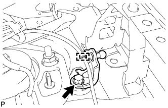
Install the hood support bracket with the bolt.
- Torque:
- 7.5 N*m { 76 kgf*cm, 66 in.*lbf }
-
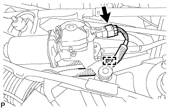
Engage the clamp.
-
-
INSTALL HOOD SUPPORT BRACKET (for Front Passenger Side)
-
Clean the threaded portion on the vehicle body with a non-residue solvent.
-
Apply adhesive to the threads of the bolt.
Adhesive Toyota Genuine Adhesive 1324, Three Bond 1324 or equivalent -
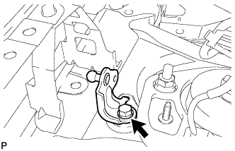
Install the hood support bracket with the bolt.
- Torque:
- 7.5 N*m { 76 kgf*cm, 66 in.*lbf }
-
-
INSTALL HOOD SUPPORT ASSEMBLY
Note
-
Avoid touching the piston rod as much as possible to prevent foreign matter from attaching to it. Be sure to hold the cylinder while servicing.
-
Do not wear cotton gloves or other similar materials when handling the piston rod. Fibers may attach to the rod and result in gas leaks.
-
In order to prevent the piston rod from deforming, do not apply any horizontal load to the door stay.
-
When reusing the back door stay assembly:
-
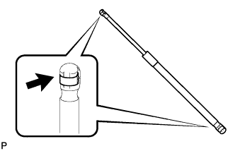
Install the 2 stop rings to the hood support assembly.
-
-
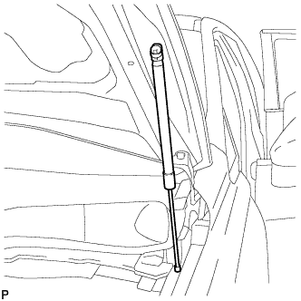
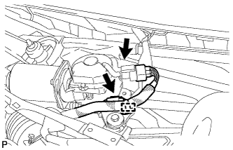
Install the hood support assembly.
Note
Install the hood support assembly while supporting the hood by hand.
-
Check that the hood support assembly is engaged in the ball joint and it cannot be pulled out.
-
-
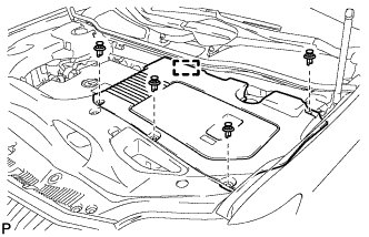
INSTALL OUTER COWL TOP PANEL SUB-ASSEMBLY
-
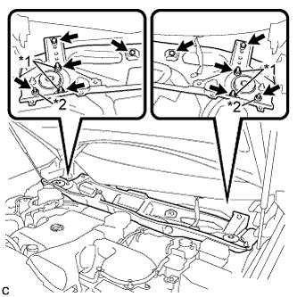
Install the outer cowl top panel sub-assembly with the 4 bolts, 4 nuts*1 and 2 nuts*2.
- Torque:
- Nut*1
- 85 N*m { 867 kgf*cm, 63 ft.*lbf }
- Nut*2
- 5.5 N*m { 56 kgf*cm, 49 in.*lbf }
- Bolt
- 5.5 N*m { 56 kgf*cm, 49 in.*lbf }
-
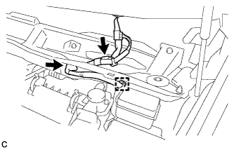
Engage the grommet and clamp.
-
Connect the connector (w/ Windshield Deicer).
-
-
INSTALL FRONT SHOCK ABSORBER CAP LH (w/ Air Suspension)
-
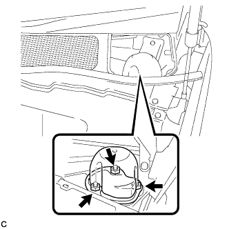
Install the front shock absorber cap with the 3 nuts.
- Torque:
- 14 N*m { 143 kgf*cm, 10 ft.*lbf }
-
-
INSTALL FRONT SHOCK ABSORBER CAP RH (w/ Air Suspension)
Tech Tips
Use the same procedure for the RH side and LH side.
-
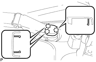
INSTALL WINDSHIELD WIPER MOTOR AND LINK ASSEMBLY
-
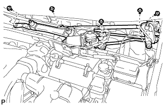
Install the windshield wiper motor and link assembly with the 5 bolts.
- Torque:
- 7.0 N*m { 71 kgf*cm, 62 in.*lbf }
Note
Be careful not to damage the windshield when installing the windshield wiper motor and link assembly.
-
w/o Deicer:
-
Engage the clamp.
-
Connect the connector.
-
-
w/ Deicer:
-
Engage the clamp.
-
Connect each connector.
-
-
-
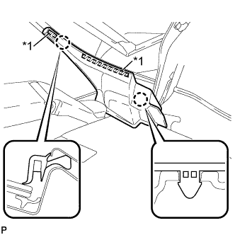
INSTALL COWL TOP VENTILATOR LOUVER SUB-ASSEMBLY
-
Engage the 10 guides.
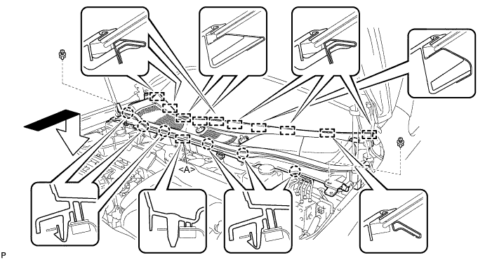
-
Engage the 6 claws and guide <A> as shown in the illustration.
-
Install the 2 clips to cowl top ventilator louver sub-assembly.
-
-
INSTALL FRONT WIPER ARM AND BLADE ASSEMBLY RH
-
Operate the wiper and stop the windshield wiper motor at the automatic stop position.
-
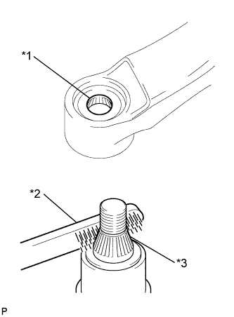
Text in Illustration *1 Wiper Arm Serration *2 Wire Brush *3 Wiper Pivot Serration When reusing the front wiper arm and blade assembly RH:
-
Clean the wiper arm serrations.
-
-
When reusing the windshield wiper link assembly:
-
Clean the wiper pivot serrations with a wire brush.
-
-
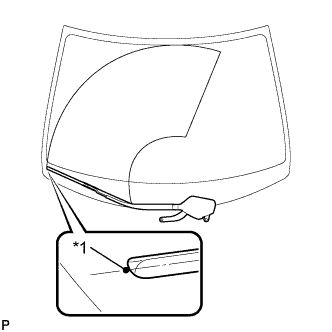
Text in Illustration *1 Ceramic Dot Install the front wiper arm and blade assembly RH with the 2 nuts to the position shown in the illustration.
- Torque:
- 24 N*m { 245 kgf*cm, 18 ft.*lbf }
Tech Tips
While holding the tip of the wiper blade on the glass at approximately 20 mm above the ceramic dot, press down on the wiper arm and tighten the nut. Then raise and lower the wiper arm a few times to confirm that it has settled to the specified position.
-
-
INSTALL FRONT WIPER ARM AND BLADE ASSEMBLY LH
-

Text in Illustration *1 Wiper Arm Serration *2 Wire Brush *3 Wiper Pivot Serration When reusing the front wiper arm and blade assembly LH:
-
Clean the wiper arm serrations.
-
-
When reusing the windshield wiper link assembly:
-
Clean the wiper pivot serrations with a wire brush.
-
-
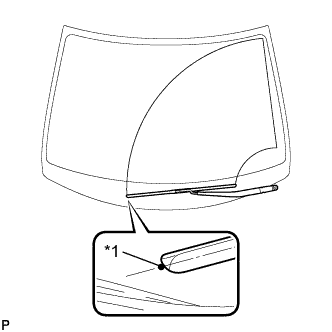
Text in Illustration *1 Ceramic Dot Install the front wiper arm and blade assembly LH with the nut to the position shown in the illustration.
- Torque:
- 24 N*m { 245 kgf*cm, 18 ft.*lbf }
Tech Tips
Hold the wiper arm by hand while tightening the nut.
-
Operate the front wipers while spraying washer fluid on the windshield glass. Make sure that the front wipers function properly and there is no interference with the vehicle body.
-
-
INSTALL FRONT WIPER ARM HEAD CAP
-
Engage the 3 claws to install the front wiper arm head cap.
-
-
INSTALL FRONT FENDER TO COWL SIDE SEAL LH
-
Wipe off any tape adhesive residue with cleaner.
-
Text in Illustration *1 Double-sided Tape Engage the 2 claws and install a new front fender to cowl side seal LH.
-
-
INSTALL FRONT FENDER TO COWL SIDE SEAL RH
Tech Tips
Use the same procedure for the RH side and LH side.
-
INSTALL FRONT FENDER TOP REINFORCEMENT SUB-ASSEMBLY LH
-
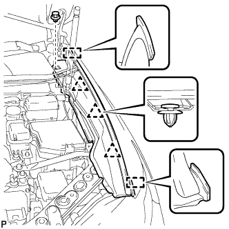
Engage the 3 clips and 2 guides.
-
Install the front fender top reinforcement sub-assembly LH with the clip.
-
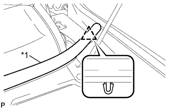
Text in Illustration *1 Hood to Cowl Top Seal Engage the clip to the hood to cowl top seal to the front fender top reinforcement sub-assembly LH.
-
-
INSTALL FRONT FENDER TOP REINFORCEMENT SUB-ASSEMBLY RH
Tech Tips
Use the same procedure for the RH side and LH side.
-
INSTALL COOL AIR INTAKE DUCT SEAL
-
Install the cool air intake duct seal with the 6 clips.
-
-
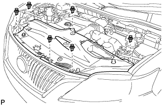
INSTALL ENGINE ROOM SIDE COVER
-
Install the engine room side cover with the 4 clips.
-
-
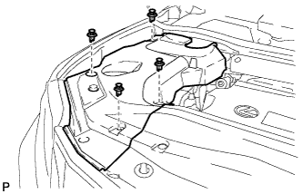
INSTALL ENGINE ROOM SIDE COVER LH
-
Engage the guide.
-
Install the engine room side cover LH with the 4 clips.
-