HOOD ADJUSTMENT

Tech Tips
-
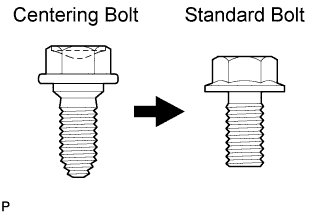
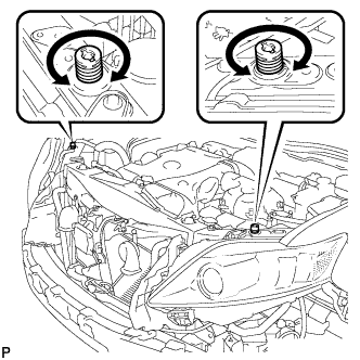
Centering bolts are used to mount the hood hinge and hood lock. The hood and hood lock cannot be adjusted with the centering bolts installed. Substitute the centering bolts with standard bolts when making adjustments.
-
Specified torque for standard bolts is shown in the standard bolt chart Click here.
-
REMOVE FRONT BUMPER ASSEMBLY
Tech Tips
Refer to the procedure up to Remove Front Bumper Assembly Click here.
-
REMOVE MILLIMETER WAVE RADAR SENSOR ASSEMBLY (w/ Dynamic Radar Cruise Control System)
-
Disconnect the connector.
-
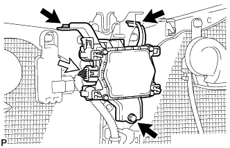
Remove the 3 bolts and the millimeter wave radar sensor assembly.
-
-
INSPECT HOOD SUB-ASSEMBLY
-
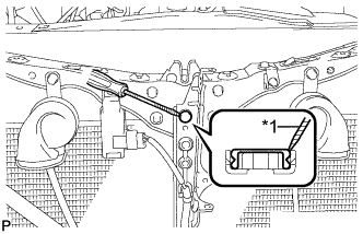
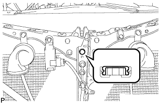
Check that the clearance measurements of areas *1 through *7 are within each standard range.
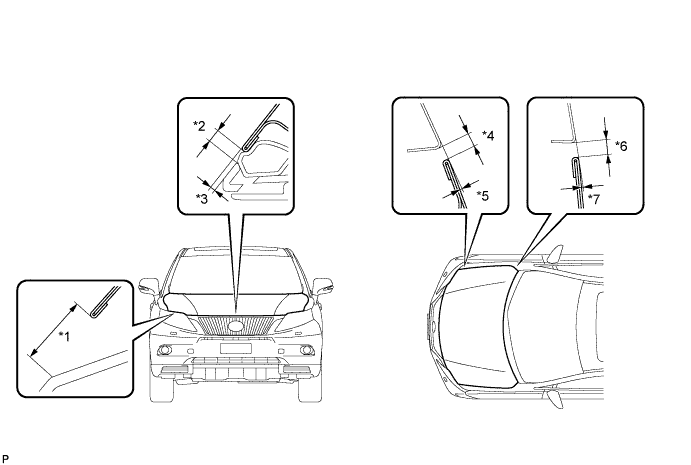
Standard Clearance Area Measurement Area Measurement *1 18.3 to 21.3 mm (0.720 to 0.839 in.) *2 3.5 to 6.5 mm (0.138 to 0.256 in.) *3 0 to 3.0 mm (0 to 0.118 in.) *4 2.3 to 5.3 mm (0.0905 to 0.209 in.) *5 -1.5 to 1.5 mm (-0.0591 to 0.0591 in.) *6 2.7 to 5.7 mm (0.106 to 0.224 in.) *7 -1.5 to 1.5 mm (-0.0591 to 0.0591 in.) - -
-
-
ADJUST HOOD SUB-ASSEMBLY
-
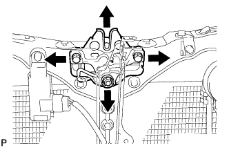
Horizontally and vertically adjust the hood.
-
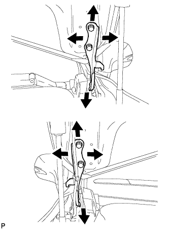
Loosen the 4 hinge bolts of the hood.
-
Adjust the clearance between the hood and front fender by moving the hood.
-
Tighten the 4 hinge bolts after the adjustment.
- Torque:
- 13 N*m { 133 kgf*cm, 10 ft.*lbf }
-
-
Adjust the height of the front end of the hood using the cushion rubbers.
-
Adjust the 2 cushion rubbers so that the heights of the hood and fender are aligned.
Tech Tips
Raise or lower the front end of the hood by turning the 2 cushion rubbers.
-
-
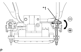
Adjust the hood lock.
-
Text in Illustration *1 Protective Tape Using a screwdriver, remove the hood lock nut cap.
Tech Tips
Tape the screwdriver tip before use.
-
Loosen the 2 bolts and hood lock nut.
-
Adjust the hood lock and tighten the 2 bolts and hood lock nut.
- Torque:
- 8.0 N*m { 82 kgf*cm, 71 in.*lbf }
-
Check that the striker can engage with the hood lock smoothly.
-
-
Install a new hood lock nut cap.
-
-
INSTALL MILLIMETER WAVE RADAR SENSOR ASSEMBLY (w/ Dynamic Radar Cruise Control System)
-
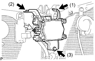
Tighten the 3 bolts on the millimeter wave radar sensor assembly.
- Torque:
- 5.5 N*m { 56 kgf*cm, 49 in.*lbf }
Tech Tips
Tighten the bolts in the order indicated in the illustration.
-
Connect the connector.
-
-
INSTALL FRONT BUMPER ASSEMBLY
Tech Tips
Refer to the procedure from Install Front Bumper Assembly Click here.
-
ADJUST MILLIMETER WAVE RADAR SENSOR ASSEMBLY (w/ Dynamic Radar Cruise Control System)
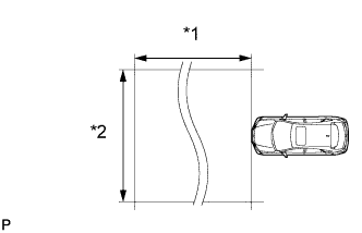
Text in Illustration *1 Approx. 10 m *2 Approx. 14 m CAUTION:
Exposure to radio frequency emissions is hazardous to your health. It is hazardous to be within 20 cm (7.87 in.) of the device's radio frequency aperture.
Note
-
This device complies with FCC radio frequency emission regulations.
-
Perform measurements on a level surface.
-
Make sure that no large pieces of metal are within a 10 m (32.8 ft.) x 14 m (45.9 ft.) area in front of the vehicle. If possible, the surrounding area should also be free of large metal objects.
-
Before adjusting the radar beam axis, prepare the vehicle as follows.
-
Check the tire pressure and adjust it if necessary.
-
Remove all excess weight from the vehicle (luggage, heavy objects, etc.).
-
-
w/ Air Suspension:
Adjust the vehicle's height to the standard height.
-
Check and adjust the vertical direction of the radar sensor.
-
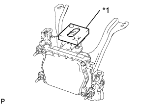
Text in Illustration *1 Level Remove dust, oil and foreign matter from the radar sensor's level rack.
-
Set a level on the radar sensor's level rack.
-
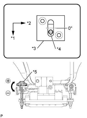
Text in Illustration *1 FR *2 LH *3 Level *4 Air Bubble *5 Bolt A Check that the level's air bubble is within the red frame.
OK Level's air bubble is within red frame. If the bubble is not within the red frame, use a screwdriver to adjust bolt A until the level's air bubble is within the red frame.
Tech Tips
-
The adjustable range within the red frame of the level is +/-0.2°.
-
The target angle is +0.2° (upward angle of 0.2°).
Result Adjustment Direction Adjustment Procedure Adjustment Angle Vertical adjustment Upward direction: Turn bolt A to negative (-) side For every 1.4 rotations of adjustment bolt, sensor moves about 1° Downward direction: Turn bolt A to positive (+) side -
-
-
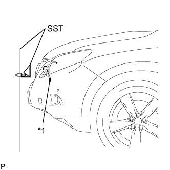
Text in Illustration *1 Millimeter Wave Radar Sensor Adjust the reflector height.
-
Adjust the reflector so that the center of SST reflector is the same height as the millimeter wave radar sensor.
- SST
- 09870-60000 ( 09870-60010 )
- 09870-60040
Tech Tips
Prepare a 10 m (32.8 ft.) string, a string with a sharp-pointed weight (plumb bob), and a 5 m (16.4 ft.) tape measure.
-
-
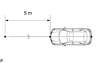
Place the reflector.
-
Hang the string (with weight) from the center of the vehicle's rear emblem. Mark the vehicle's rear center point on the ground. Repeat for the front of the vehicle.
-
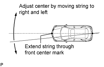
Set one end of the 10 m (32.8 ft.) string on the vehicle's rear center point. Run the string over the vehicle's front center point to a position 5 m (16.4 ft.) beyond the vehicle's front center point, as shown in the illustration. Mark the 5 m (16.4 ft.) position.
-
Using a tape measure, measure 15 mm (0.591 in.) to the right of the 5 m (16.4 ft.) position. Place the reflector at that position.
Note
Perform the operation as precisely as possible.
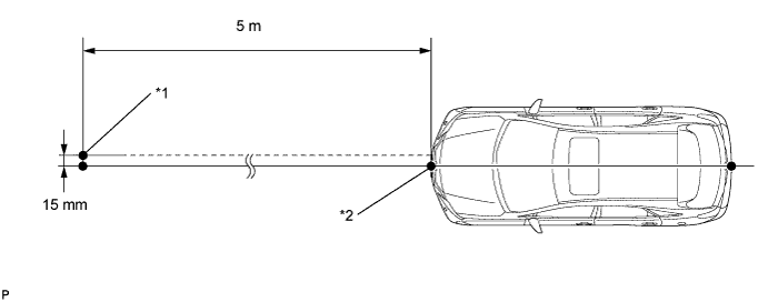
Text in Illustration *1 Reflector Placement Point *2 Millimeter Wave Radar Sensor Position
-
-
Check the radar beam axis.
-
Connect the intelligent tester to the DLC3.
-
Turn the power switch on (IG).
-
Turn the intelligent tester on, and turn the cruise control main switch on.
-
Select "Auto" from the intelligent tester display screen. *1
-
Select "Radar Cruise" from the display screen.
-
Select "Radar Cruise" from the display screen.
-
Select "Utility" from the display screen.
-
Select "Beam Axis Adjustment" from the display screen.
-
Follow the tester display, and select "Next".
CAUTION:
Do not come within 20 cm (7.87 in.) of the radar sensor.
Note
-
Turn the cruise control main switch on before pressing Next.
-
Make sure there is at least 20 cm (7.87 in.) between the radar sensor and any nearby individuals.
-
-
Check the following items on the laser cruise divergence data screen.
CAUTION:
While using the intelligent tester's beam axis adjustment mode, the actual direction and angle of the radar sensor may be different from the intelligent tester's data. In such a case, the deviation is displayed on the combination meter's multi-information display.
-
Confirm that the distance value is approximately 5 m (16.4 ft.).
Tech Tips
-
A value between 0.0 m (0.0 ft.) and 6.3 m (20.7 ft.) is indicated.
-
If the distance is 0.0 m (0.0 ft.), the sensor cannot detect the target. Reconfirm that there is no metal in the specified area in front of the vehicle (refer to the NOTICE at the beginning of this adjustment procedure).
-
-
Confirm that the left/right side value is between 0.0 m (0.0 ft.) and 6.3 m (20.7 ft.).
Tech Tips
If the distance is 0.0 m (0.0 ft.), the sensor cannot detect the target. Reconfirm that there is no metal in the specified area in front of the vehicle (refer to the NOTICE at the beginning of this adjustment procedure).
-
-
-
Check and adjust the horizontal direction of the radar sensor.
-
Check that the divergence of the radar beam axis is 0°.
Standard 0° (Both right and left) If the axis is not as specified, use a screwdriver to adjust bolt B until the divergence of the radar beam axis is 0°.
-
Text in Illustration *1 Bolt B Based on the measured divergence of the beam axis, turn and adjust bolt B for horizontal adjustment of the millimeter wave radar sensor using a screwdriver.
Result Adjustment Direction Adjustment Procedure Adjustment Angle Horizontal adjustment Right direction: Turn bolt B to positive (+) side. For every 2.5 rotations of adjustment bolt, sensor moves about 1° Left direction: Turn bolt B to negative (-) side. Tech Tips
-
If "LEFT SIDE: 1.0°" is displayed, the divergence is 1.0° in the left direction. Turn bolt B approximately 2.5 turns to the negative (-) side.
-
If the value does not change to 0°, it is possible that the sensor is aiming at something different. Reconfirm that there are no reflective materials in the surrounding area.
-
-
Select "Next". The driving learning value is automatically reset.
Tech Tips
A buzzer will sound for 10 seconds or more.
-
Disconnect the intelligent tester from the DLC3.
-
-
Recheck and readjust the vertical direction of the radar sensor.
-
Text in Illustration *1 Level Set a level on the radar sensor's level rack.
-
Text in Illustration *1 FR *2 LH *3 Level *4 Air Bubble *5 Bolt A Check that the level's air bubble is within the red frame.
OK Level's air bubble is within the red frame. If the bubble is not within the red frame, use a screwdriver to adjust bolt A until the level's air bubble is within the red frame.
Tech Tips
-
The adjustable range within the red frame is +/-0.2°.
-
The target angle is +0.2° (upward angle of 0.2°).
Result Adjustment Direction Adjustment Procedure Adjustment Angle Vertical adjustment Upward direction: Turn bolt A to negative (-) side For every 1.4 rotations of adjustment bolt, sensor moves about 1° Downward direction: Turn bolt A to positive (+) side -
-
-