POWER BACK DOOR SYSTEM Touch Sensor Circuit
DESCRIPTION
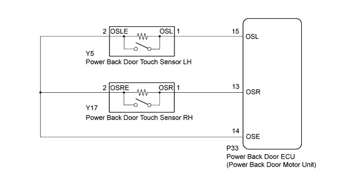
When the power back door ECU (power back door motor unit) receives a jam signal from the touch sensor while the power back door is operating, the ECU reverses the back door operation and opens the door.
WIRING DIAGRAM
INSPECTION PROCEDURE
PROCEDURE
-
READ VALUE USING INTELLIGENT TESTER (POWER BACK DOOR TOUCH SENSOR)
-
Connect the intelligent tester to the DLC3.
-
Turn the power switch on (IG).
-
Turn the intelligent tester on.
-
Enter the following menus: Body / Back Door / Data List.
-
Check the Data List to determine if the power back door touch sensor functions properly.
Back Door (Power Back Door ECU (Power Back Door Motor Unit)) Tester Display Measurement Item/Range Normal Condition Diagnostic Note PBD Touch Sensor (Left) Power back door touch sensor LH signal/ON, OFF or Open ON: Power back door touch sensor LH is pressed
OFF: Power back door touch sensor LH is not pressed
Open: Power back door touch sensor LH circuit open
- PBD Touch Sensor (Right) Power back door touch sensor RH signal/ON, OFF or Open ON: Power back door touch sensor RH is pressed
OFF: Power back door touch sensor RH is not pressed
Open: Power back door touch sensor RH circuit open
- Result Result Proceed to ON and OFF function is normal A ON and OFF function is not normal, or Open is displayed for LH touch sensor B ON and OFF function is not normal, or Open is displayed for RH touch sensor C
B 
CHECK POWER BACK DOOR TOUCH SENSOR LH (POWER BACK DOOR TOUCH SENSOR LH - BODY GROUND) Click here
C
CHECK POWER BACK DOOR TOUCH SENSOR RH (POWER BACK DOOR TOUCH SENSOR RH - BODY GROUND) Click here
A 
END
-
-
CHECK POWER BACK DOOR TOUCH SENSOR LH (POWER BACK DOOR TOUCH SENSOR LH - BODY GROUND)
-
Text in Illustration *1 Component without harness connected
(Power Back Door Touch Sensor LH)
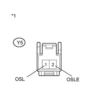
Disconnect the Y5 power back door touch sensor LH connector.
-
Measure the resistance according to the value(s) in the table below.
Standard Resistance Tester Connection Condition Specified Condition Y5-1 (OSL) - Body ground Always 10 kΩ or higher Y5-2 (OSLE) - Body ground Always 10 kΩ or higher Tech Tips
Perform this inspection with the touch sensor installed on the vehicle.
NG 
REPLACE POWER BACK DOOR TOUCH SENSOR LH Click here
OK 
-
-
INSPECT POWER BACK DOOR TOUCH SENSOR LH
-
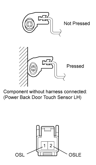
Remove the power back door touch sensor LH Click here.
-
Measure the resistance according to the value(s) in the table below.
Standard Resistance Tester Connection Condition Specified Condition 1 (OSL) - 2 (OSLE) Not pressed 950 to 1050 Ω 1 (OSL) - 2 (OSLE) Pressed Below 100 Ω
NG
REPLACE POWER BACK DOOR TOUCH SENSOR LH Click here
OK
-
-
CHECK HARNESS AND CONNECTOR (TOUCH SENSOR LH - POWER BACK DOOR ECU AND BODY GROUND)
-
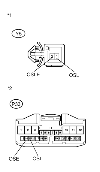
Text in Illustration *1 Front view of wire harness connector
(to Power Back Door Touch Sensor LH)
*2 Front view of wire harness connector
(to Power Back Door ECU)
Disconnect the Y5 power back door touch sensor LH connector and P33 power back door ECU connector.
-
Measure the resistance according to the value(s) in the table below.
Standard Resistance Tester Connection Condition Specified Condition Y5-1 (OSL) - P33-15 (OSL) Always Below 1 Ω Y5-2 (OSLE) - P33-14 (OSE) Always Below 1 Ω Y5-1 (OSL) - Body ground Always 10 kΩ or higher
NG
REPAIR OR REPLACE HARNESS OR CONNECTOR
OK
REPLACE POWER BACK DOOR ECU (POWER BACK DOOR MOTOR UNIT) Click here
-
-
CHECK POWER BACK DOOR TOUCH SENSOR RH (POWER BACK DOOR TOUCH SENSOR RH - BODY GROUND)
-
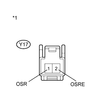
Text in Illustration *1 Component without harness connected
(Power Back Door Touch Sensor RH)
Disconnect the Y17 power back door touch sensor RH connector.
-
Measure the resistance according to the value(s) in the table below.
Standard Resistance Tester Connection Condition Specified Condition Y17-1 (OSR) - Body ground Always 10 kΩ or higher Y17-2 (OSRE) - Body ground Always 10 kΩ or higher Tech Tips
Perform this inspection with the touch sensor installed on the vehicle.
NG
REPLACE POWER BACK DOOR TOUCH SENSOR RH Click here
OK
-
-
INSPECT POWER BACK DOOR TOUCH SENSOR RH
-
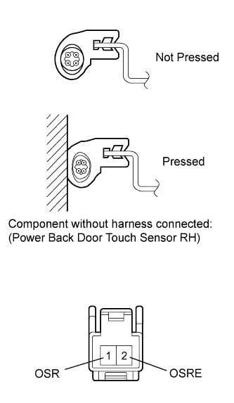
Remove the power back door touch sensor RH Click here.
-
Measure the resistance according to the value(s) in the table below.
Standard Resistance Tester Connection Condition Specified Condition 1 (OSR) - 2 (OSRE) Not pressed 950 to 1050 Ω 1 (OSR) - 2 (OSRE) Pressed Below 100 Ω
NG
REPLACE POWER BACK DOOR TOUCH SENSOR RH Click here
OK
-
-
CHECK HARNESS AND CONNECTOR (TOUCH SENSOR RH - POWER BACK DOOR ECU AND BODY GROUND)
-
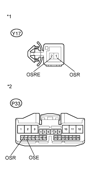
Text in Illustration *1 Front view of wire harness connector
(to Power Back Door Touch Sensor RH)
*2 Front view of wire harness connector
(to Power Back Door ECU)
Disconnect the Y17 power back door touch sensor RH connector and P33 power back door ECU connector.
-
Measure the resistance according to the value(s) in the table below.
Standard Resistance Tester Connection Condition Specified Condition Y17-1 (OSR) - P33-13 (OSR) Always Below 1 Ω Y17-2 (OSRE) - P33-14 (OSE) Always Below 1 Ω Y17-1 (OSR) - Body ground Always 10 kΩ or higher
NG
REPAIR OR REPLACE HARNESS OR CONNECTOR
OK
REPLACE POWER BACK DOOR ECU (POWER BACK DOOR MOTOR UNIT) Click here
-