LIN COMMUNICATION SYSTEM, Diagnostic DTC:B2786

| DTC Code | DTC Name |
|---|---|
| B2786 | No Response from Steering Lock ECU |
DESCRIPTION
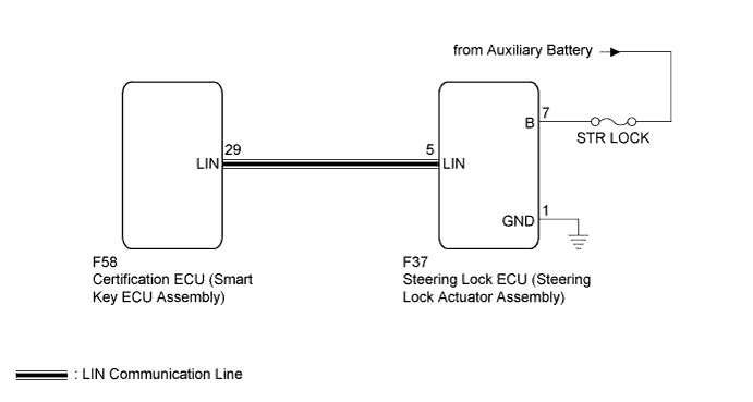
This DTC is stored when LIN communication between the certification ECU (smart key ECU assembly) and steering lock ECU (steering lock actuator assembly) stops for more than 10 seconds.
| DTC No. | DTC Detection Condition | Trouble Area |
|---|---|---|
| B2786 | No communication between steering lock ECU (steering lock actuator assembly) and certification ECU (smart key ECU assembly) for more than 10 seconds. |
|
WIRING DIAGRAM
INSPECTION PROCEDURE
Note
-
If the certification ECU (smart key ECU assembly) is replaced, register the key.
-
If the steering lock ECU (steering lock actuator assembly) is replaced, register the ECU code.
-
When using the intelligent tester to troubleshoot with the power switch off:
Connect the intelligent tester to the DLC3, and turn the courtesy switch on and off at 1.5-second intervals until communication between the intelligent tester and vehicle begins.
PROCEDURE
-
CHECK HARNESS AND CONNECTOR (STEERING LOCK ECU - BATTERY AND BODY GROUND)
-
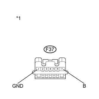
Text in Illustration *1 Front view of wire harness connector
(to Steering Lock ECU (Steering Lock Actuator Assembly))
Disconnect the F37 steering lock ECU connector.
-
Measure the resistance and voltage according to the value(s) in the table below.
Standard Resistance Tester Connection Condition Specified Condition F37-1 (GND) - Body ground Always Below 1 Ω Standard Voltage Tester Connection Condition Specified Condition F37-7 (B) - Body ground Always 11 to 14 V
NG 
REPAIR OR REPLACE HARNESS OR CONNECTOR, OR REPLACE FUSE
OK 
-
-
CHECK HARNESS AND CONNECTOR (CERTIFICATION ECU - STEERING LOCK ECU)
-
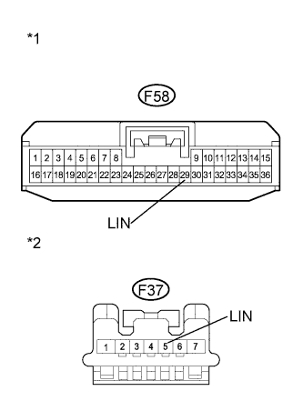
Text in Illustration *1 Front view of wire harness connector
(to Certification ECU (Smart key ECU assembly))
*2 Front view of wire harness connector
(to Steering lock ECU (Steering Lock Actuator Assembly))
Disconnect the F58 certification ECU (smart key ECU assembly) connector.
-
Measure the resistance according to the value(s) in the table below.
Standard Resistance Tester Connection Condition Specified Condition F58-29 (LIN) - F37-5 (LIN) Always Below 1 Ω F58-29 (LIN) - Body ground Always 10 kΩ or higher
NG
REPAIR OR REPLACE HARNESS OR CONNECTOR
OK
-
-
REPLACE STEERING LOCK ECU (STEERING LOCK ACTUATOR ASSEMBLY)
-
Replace the steering lock ECU (steering lock actuator assembly) Click here.
NEXT
-
-
CHECK DTC OUTPUT
-
Clear the DTC Click here.
-
Recheck for DTCs.
OK DTC B2786 is not output.
NG
REPLACE CERTIFICATION ECU (SMART KEY ECU ASSEMBLY)
OK 
END (STEERING LOCK ECU WAS DEFECTIVE)
-