LIN COMMUNICATION SYSTEM, Diagnostic DTC:B1249

| DTC Code | DTC Name |
|---|---|
| B1249 | Double Locking ECU Communication Stop |
DESCRIPTION
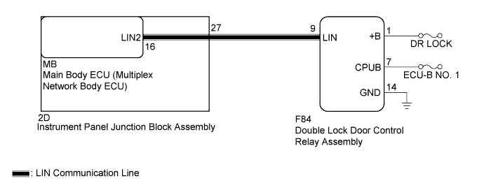
The main body ECU (multiplex network body ECU) stores a DTC when communication with the double lock door control relay assembly is interrupted for 10 seconds or more.
| DTC No. | DTC Detection Condition | Trouble Area |
|---|---|---|
| B1249 | Communication between double lock door control relay assembly and main body ECU (multiplex network body ECU) interrupted for 10 seconds or more, or communication wire malfunction. |
|
WIRING DIAGRAM
INSPECTION PROCEDURE
Tech Tips
-
When using the intelligent tester, repeatedly turn either front door courtesy light switch off-and-on at intervals of 1.5 seconds or less, until communication between the intelligent tester and vehicle begins.
-
When the main body ECU (multiplex network body ECU) has been replaced with a new part, and the cable from negative auxiliary battery terminal (-) is reconnected, the power switch condition will be on (IG). Also, when the auxiliary battery has been removed and installed, the condition will be the same as it was before the auxiliary battery was disconnected.
Note
Inspect the fuses for circuits related to this system before performing the following inspection procedure.
PROCEDURE
-
INSPECT INSTRUMENT PANEL JUNCTION BLOCK ASSEMBLY
-
Remove the instrument panel junction block assembly Click here.
-
Remove the main body ECU (multiplex network body ECU) from the instrument panel junction block assembly.
-
Measure the resistance according to the value(s) in the table below.
Tech Tips
This inspection is to check the LIN line in the instrument panel junction block assembly that connects the wire harness to the built-in main body ECU (multiplex network body ECU).
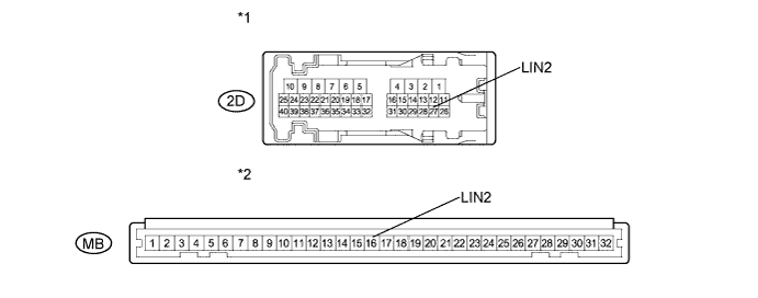
Standard Resistance Tester Connection Condition Specified Condition 2D-27 (LIN2) - MB-16 (LIN2) Always Below 1 Ω 2D-27 (LIN2) - Body ground Always 10 kΩ or higher Text in Illustration *1 Component without harness connected
(Instrument Panel Junction Block Assembly)
*2 Component without harness connected
(Instrument Panel Junction Block Assembly)
NG 
CHECK DTC OUTPUT Click here
OK 
-
-
CHECK HARNESS AND CONNECTOR
-
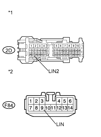
Text in Illustration *1 Front view of wire harness connector
(to Instrument Panel Junction Block Assembly)
*2 Front view of wire harness connector
(to Double Lock Door Control Relay Assembly)
Disconnect the F84 double lock door control relay assembly connector.
-
Measure the resistance according to the value(s) in the table below.
Standard Resistance Tester Connection Condition Specified Condition 2D-27 (LIN2) - F84-9 (LIN) Always Below 1 Ω 2D-27 (LIN2) - Body ground Always 10 kΩ or higher
NG
REPAIR OR REPLACE HARNESS OR CONNECTOR
OK
-
-
CHECK HARNESS AND CONNECTOR
-
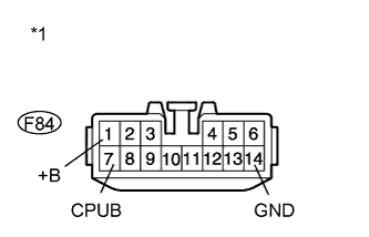
Text in Illustration *1 Front view of wire harness connector
(to Double Lock Door Control Relay Assembly)
Measure the voltage according to the value(s) in the table below.
Standard Voltage Tester Connection Condition Specified Condition F84-1 (+B) - Body ground Always 11 to 14 V F84-7 (CPUB) - Body ground Always 11 to 14 V -
Measure the resistance according to the value(s) in the table below.
Standard Resistance Tester Connection Condition Specified Condition F84-14 (GND) - Body ground Always Below 1 Ω
NG
REPAIR OR REPLACE HARNESS OR CONNECTOR
OK
-
-
REPLACE DOUBLE LOCK DOOR CONTROL RELAY ASSEMBLY
-
Replace the double lock door control relay assembly Click here.
NEXT
-
-
CHECK DTC OUTPUT
-
Clear the DTC Click here.
-
Recheck for DTCs.
OK DTC B1249 is not output.
NG
REPLACE MAIN BODY ECU (MULTIPLEX NETWORK BODY ECU) Click here
OK 
END (DOUBLE LOCK DOOR CONTROL RELAY WAS DEFECTIVE)
-