INTEGRATION RELAY REMOVAL

-
PRECAUTION (w/ Navigation System for HDD)
Note
After the power switch is turned off, the display and navigation module display (HDD navigation system) records various types of memory and settings. As a result, after turning the power switch off, make sure to wait for the time specified in the following table before disconnecting the cable from the negative (-) battery terminal.
Waiting Time before Disconnecting Cable from Negative (-) Battery Terminal Specification Waiting Time w/o Telematics transceiver 60 sec. w/ Telematics transceiver 120 sec. -
REMOVE REAR DECK FLOOR BOX
-

Remove the 3 clips and the rear deck floor box.
-
-
DISCONNECT CABLE FROM NEGATIVE BATTERY TERMINAL
Note
When disconnecting the cable, some systems need to be initialized after the cable is reconnected Click here.
-
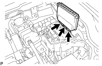
DISCONNECT RELAY BLOCK
-
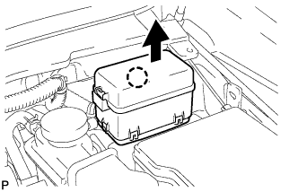
Disengage the claw and disconnect the relay block as shown in the illustration.
-
-
REMOVE NO. 1 RELAY BLOCK COVER
-
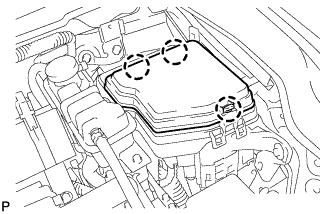
Disengage the 3 claws and remove the upper No. 1 relay block cover.
-
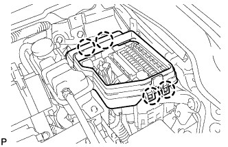
Disengage the 4 claws and remove the lower No. 1 relay block cover.
-
-
REMOVE ENGINE ROOM JUNCTION BLOCK ASSEMBLY
-
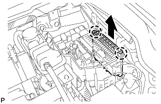
Disengage the 2 claws and pull up the engine room junction block assembly as shown in the illustration.
-
Disconnect the 3 connectors and remove the engine room junction block assembly.
-