MAIN BODY ECU INSTALLATION

-
INSTALL MAIN BODY ECU (MULTIPLEX NETWORK BODY ECU) (for LHD)
Note
-
Make sure that no foreign objects get on the connecting surfaces.
-
Do not touch the ECU connector.
-
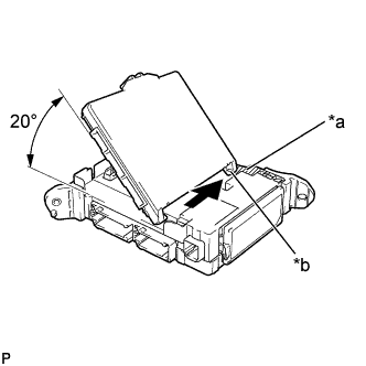
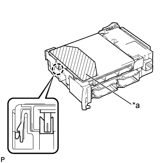
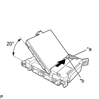
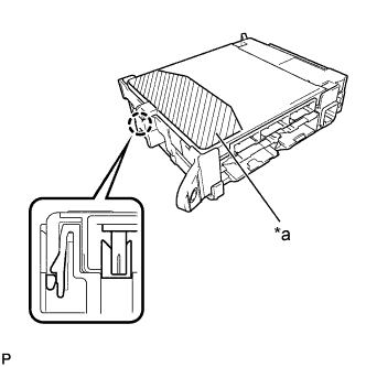
Text in Illustration *a Housing sidewall *b Guide part Insert the main body ECU (multiplex network body ECU) up to the position where it contacts the housing sidewall of the guide as shown in the illustration.
Tech Tips
Make sure to keep the angle 20° or more as shown in the illustration.
-
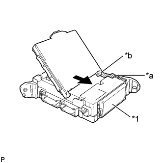
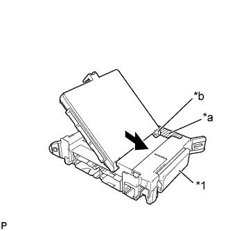
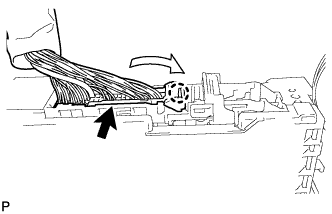
Text in Illustration *1 Junction block fuses *a Housing sidewall *b Guide part Slide the guide of the main body ECU (multiplex network body ECU) along the housing sidewall toward the junction block fuses as shown in the illustration.
-
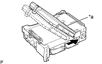
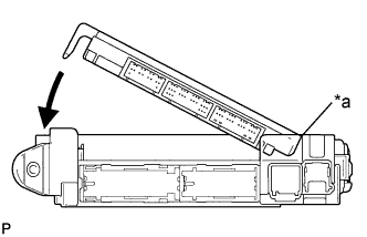
Text in Illustration *a Side A Slide the main body ECU (multiplex network body ECU) so that it contacts side A as shown in the illustration.
Note
Do not apply excessive force to the main body ECU (multiplex network body ECU).
-
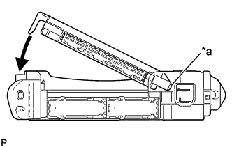
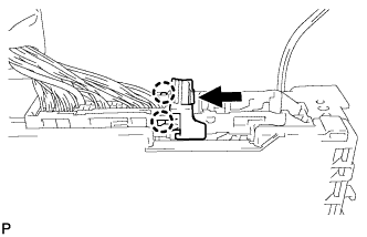
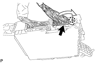
Text in Illustration *a Side A contact portion While contacting the main body ECU (multiplex network body ECU) to side A of the junction block (point of rotation), rotate it downward as shown in the illustration.
-
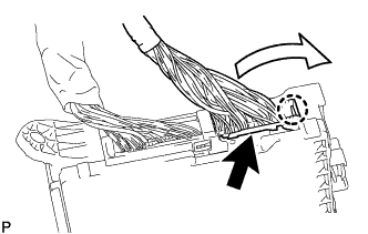
Text in Illustration *a Push Area Press the push area until the claw engages to install the main body ECU (multiplex network body ECU).
Note
-
Make sure to press only the push area.
-
Confirm the engagement of the main body ECU (multiplex network body ECU) and junction block by listening for the lock sound.
Tech Tips
If a lock sound cannot be heard, visually check the lock part engagement. The engagement can also be confirmed if the main body ECU (multiplex network body ECU) and junction block are flush.
-
-
-
INSTALL MAIN BODY ECU (MULTIPLEX NETWORK BODY ECU) (for RHD)
Note
-
Make sure that no foreign objects get on the connecting surfaces.
-
Do not touch the ECU connector.
-
Text in Illustration *a Housing sidewall *b Guide part Insert the main body ECU (multiplex network body ECU) up to the position where it contacts the housing sidewall of the guide as shown in the illustration.
Tech Tips
Make sure to keep the angle 20°or more as shown in the illustration.
-
Text in Illustration *1 Junction block fuses *a Housing sidewall *b Guide part Slide the guide of the main body ECU (multiplex network body ECU) along the housing sidewall toward the junction block fuses as shown in the illustration.
-

Text in Illustration *a Side A Slide the main body ECU (multiplex network body ECU) so that it contacts side A as shown in the illustration.
Note
Do not apply excessive force to the main body ECU (multiplex network body ECU).
-
Text in Illustration *a Side A contact portion While contacting the main body ECU (multiplex network body ECU) to side A of the junction block (point of rotation), rotate it downward as shown in the illustration.
-
Text in Illustration *a Push Area Press the push area until the claw engages to install the main body ECU (multiplex network body ECU).
Note
-
Make sure to press only the push area.
-
Confirm the engagement of the main body ECU (multiplex network body ECU) and junction block by listening for the lock sound.
Tech Tips
If a lock sound cannot be heard, visually check the lock part engagement. The engagement can also be confirmed if the main body ECU (multiplex network body ECU) and junction block are flush.
-
-
-
INSTALL WIRING HARNESS CLAMP BRACKET (for LHD)
-
Install the wiring harness clamp bracket to the instrument panel junction block assembly with the bolt.
- Torque:
- 13 N*m { 127 kgf*cm, 9 ft.*lbf }
-
-
INSTALL POWER MANAGEMENT CONTROL ECU (for LHD)
-
Install the power management control ECU with the 2 nuts.
- Torque:
- 7.5 N*m { 76 kgf*cm, 66 in.*lbf }
-
-
INSTALL INSTRUMENT PANEL JUNCTION BLOCK ASSEMBLY (for LHD)
-
Engage the claw to connect the connector as shown in the illustration.
-
Engage the 2 claws to lock the connector lock as shown in the illustration.
-
Engage the claw to connect the connector as shown in the illustration.
-
Install the instrument panel junction block assembly with the 2 nuts.
- Torque:
- 8.0 N*m { 82 kgf*cm, 71 in.*lbf }
-
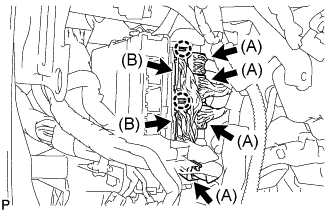
Connect the 4 connectors (A).
-
Engage the 2 claws to connect the 2 connectors (B).
-
Connect the 4 connectors.
-
-
INSTALL INSTRUMENT PANEL JUNCTION BLOCK ASSEMBLY (for RHD)
-
Engage the claw to connect the connector as shown in the illustration.
-
Engage the 2 claws to lock the connector lock as shown in the illustration.
-
Engage the claw to connect the connector as shown in the illustration.
-
Install the instrument panel junction block assembly with the bolt and nut.
- Torque:
- Bolt
- 13 N*m { 127 kgf*cm, 9 ft.*lbf }
- Nut
- 8.0 N*m { 82 kgf*cm, 71 in.*lbf }
-
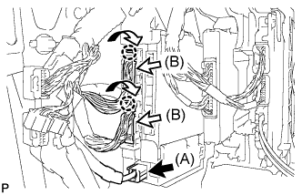
Connect the connector (A).
-
Engage the 2 claws to connect the 2 connectors (B) as shown in the illustration.
-
Connect the 3 connectors.
-
-
INSTALL GLOVE COMPARTMENT DOOR ASSEMBLY (for RHD)
-
Connect each connector.
-
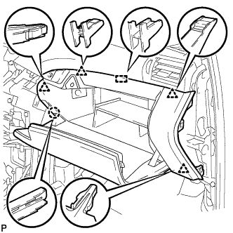
Engage the claw, 4 clips and guide.
-
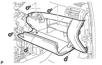
Install the glove compartment door assembly with the 5 screws <F>.
-
-
INSTALL DRIVER SIDE KNEE AIRBAG ASSEMBLY (for LHD)
-
INSTALL FRONT PASSENGER SIDE KNEE AIRBAG ASSEMBLY (for RHD)