SIDE MONITOR SYSTEM "CHK" message(s) are displayed on the SIGNAL CHECK screen.
DESCRIPTION
On the SIGNAL CHECK screen, it is possible to check if the state of signals sent to the parking assist ECU is normal Click here.
Tech Tips
-
On the SIGNAL CHECK screen, "OK" (blue) is displayed for items with a normal inspection result and input state.
-
On the SIGNAL CHECK screen, "CHK" (red) is displayed for items with an abnormal inspection result and input state.
-
Displayed items may differ depending on the specifications.
| Item | Signal Input Method | Detail | DTC Output when Abnormal Result is Displayed | Signal Receiver |
|---|---|---|---|---|
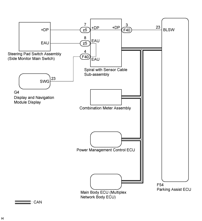
| SPEED | CAN communication | Speed signal input | DTC is output | Combination meter assembly |
| CAMERA SW | Vehicle wire harness | Steering pad switch assembly (side monitor main switch) signal input | DTC is not output | Steering pad switch assembly (Side monitor main switch) |
| BCTY | CAN communication | CAN communication condition with main body ECU (multiplex network body ECU) | DTC is output | Main body ECU (multiplex network body ECU) |
| MIRROR SW | CAN communication | Outer rear view mirror retract signal input | DTC is output |
|
| SHIFT | CAN communication | Shift signal input | DTC is output | Power management control ECU |
| STR SIG | CAN communication | Steering angle sensor signal input | DTC is output | Spiral with sensor cable sub-assembly |
| HANDLE | CAN communication | Steering position signal input | DTC is output | Main body ECU (multiplex network body ECU) |
| ENGINE | CAN communication | ENG/HV judgement signal | DTC is output | Power management control ECU |
| DEST | CAN communication | Destination information signal input | DTC is output | Main body ECU (multiplex network body ECU) |
WIRING DIAGRAM
INSPECTION PROCEDURE
Note
-
When "System initializing" is displayed on the multi-display after the cable is disconnected from the negative (-) battery terminal, correct the steering angle neutral point Click here.
-
Depending on the parts that are replaced or operations that are performed during vehicle inspection or maintenance, calibration of other systems as well as the side monitor system may be needed Click here.
-
When replacing the display and navigation module display, perform vehicle contract setting (w/ G-BOOK system) Click here.
PROCEDURE
-
CHECK DISPLAY CHECK MODE
-
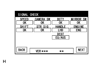
Check which items display "CHK" (red) on the SIGNAL CHECK screen.
Result Result Proceed to "MIRROR SW" displays "CHK" (red). A "CAMERA SW" displays "CHK" (red). B Any of "SPEED", "BCTY", "SHIFT", STR SIG", "HANDLE", "ENGINE" and "DEST" displays "CHK" (red). C
B 
C 
CHECK DTC OUTPUT Click here
A 
-
-
CHECK POWER MIRROR CONTROL SYSTEM (POWER RETRACT MIRROR FUNCTION)
-
Operate the mirror retract switch to check if the power retract mirror function of the outer rear view mirror assembly (passenger side) operates normally Click here.
Result Result Proceed to Power retract mirror function is normal A Power retract mirror function is abnormal B
B
GO TO POWER MIRROR CONTROL SYSTEM Click here
A 
CHECK DTC OUTPUT Click here
-
-
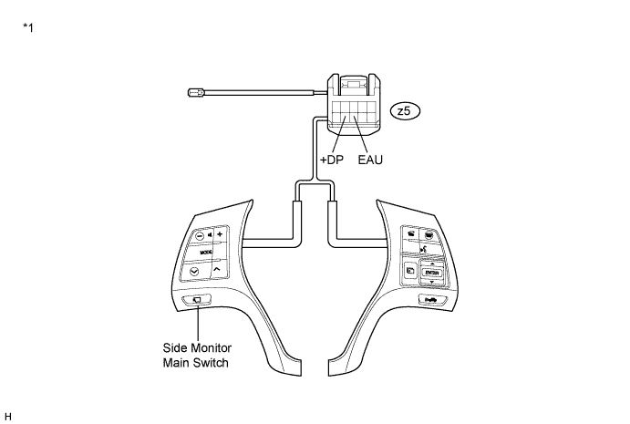
INSPECT STEERING PAD SWITCH ASSEMBLY (SIDE MONITOR MAIN SWITCH)
-
Remove the steering pad switch assembly Click here.
-
Measure the resistance according to the value(s) in the table below.
Standard Resistance Tester Connection Condition Specified Condition z5-7 (+DP) - z5-8 (EAU) Side monitor main switch pushed in Below 2.5 Ω z5-7 (+DP) - z5-8 (EAU) Side monitor main switch not pushed 10 kΩ or higher Text in Illustration *1 Component without harness connected
(Steering Pad Switch Assembly)
- -
NG
REPLACE STEERING PAD SWITCH ASSEMBLY Click here
OK
-
-
INSPECT SPIRAL WITH SENSOR CABLE SUB-ASSEMBLY
-
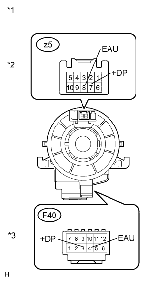
Text in Illustration *1 Component without harness connected
(Spiral with Sensor Cable Sub-assembly)
*2 Steering Pad Switch Side *3 Vehicle Side Disconnect the connectors from the steering pad switch and spiral cable.
-
Measure the resistance according to the value(s) in the table below.
Standard Resistance Tester Connection Condition Specified Condition z5-8 (EAU) - F40-4 (EAU) Center Below 1 Ω 2.5 rotations to the left 2.5 rotations to the right z5-7 (+DP) - F40-3 (+DP) Center Below 1 Ω 2.5 rotations to the left 2.5 rotations to the right Note
The spiral cable is an important part of the SRS airbag system. Incorrect removal or installation of the spiral cable may prevent the airbag from deploying. Refer to the pages shown in the brackets.
NG
REPLACE SPIRAL WITH SENSOR CABLE SUB-ASSEMBLY Click here
OK
-
-
CHECK HARNESS AND CONNECTOR (EAU)
-
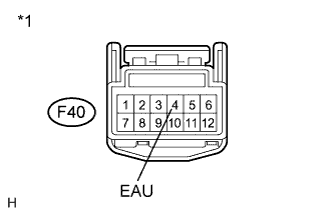
Text in Illustration *1 Front view of wire harness connector
(to Spiral with Sensor Cable Sub-assembly)
Disconnect the F40 connector from the spiral with sensor cable sub-assembly.
-
Measure the resistance according to the value(s) in the table below.
Standard Resistance Tester Connection Condition Specified Condition F40-4 (EAU) - Body ground Always Below 1 Ω
NG
OK
-
-
CHECK HARNESS AND CONNECTOR (PARKING ASSIST ECU - SPIRAL WITH SENSOR CABLE SUB-ASSEMBLY)
-
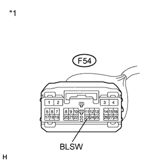
Disconnect the F54 connector from the parking assist ECU.
-
Disconnect the F40 connector from the spiral with sensor cable sub-assembly.
-
Measure the resistance according to the value(s) in the table below.
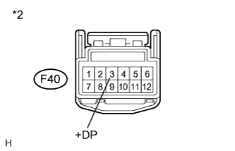
Standard Resistance Tester Connection Condition Specified Condition F54-23 (BLSW) - F40-3 (+DP) Always Below 1 Ω Text in Illustration *1 Front view of wire harness connector
(to Parking Assist ECU)
*2 Front view of wire harness connector
(to Spiral with Sensor Cable Sub-assembly)
NG
REPAIR OR REPLACE HARNESS OR CONNECTOR
OK
REPLACE PARKING ASSIST ECU Click here
-
-
CHECK HARNESS AND CONNECTOR (SPIRAL CABLE - DISPLAY AND NAVIGATION MODULE DISPLAY)
-
Disconnect the F40 connector from the spiral with sensor cable sub-assembly.
-
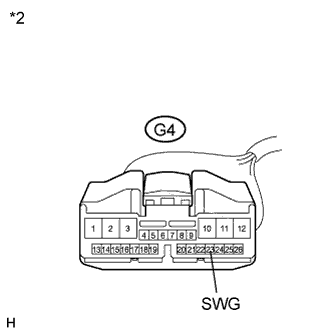
Disconnect the G4 connector from the display and navigation module display.
-
Measure the resistance according to the value(s) in the table below.
Standard Resistance Tester Connection Condition Specified Condition F40-4 (EAU) - G4-23 (SWG) Always Below 1 Ω Text in Illustration *1 Front view of wire harness connector
(to Spiral with Sensor Cable Sub-assembly)
*2 Front view of wire harness connector
(to Display and Navigation Module Display)
Result Result Proceed to OK (navigation system (for HDD)) A OK (navigation system (for DVD)) B NG C
B
REPLACE DISPLAY AND NAVIGATION MODULE DISPLAY (for DVD) Click here
C
REPAIR OR REPLACE HARNESS OR CONNECTOR
A
REPLACE DISPLAY AND NAVIGATION MODULE DISPLAY (for HDD) Click here
-