SIDE MONITOR SYSTEM Image from Camera for Side Monitor is Abnormal
DESCRIPTION
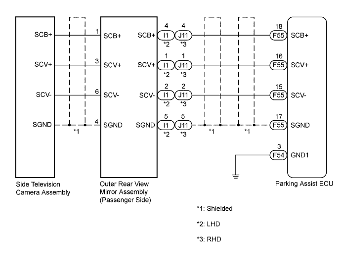
The display signal from the side television camera assembly is transmitted to the multi-display assembly via the parking assist ECU.
WIRING DIAGRAM
INSPECTION PROCEDURE
Note
-
When "System initializing" is displayed on the multi-display after the cable is disconnected from the negative (-) battery terminal, correct the steering angle neutral point Click here.
-
Depending on the parts that are replaced or operations that are performed during vehicle inspection or maintenance, calibration of other systems as well as the side monitor system may be needed Click here.
Tech Tips
Images are difficult to discern even in normal conditions if:
-
Noise may occur in the image while adjusting or retracting the outer rear view mirror assembly (passenger side).
-
Noise may occur in the image depending on electrical devices used in the cabin.
-
Noise may occur in the image if accessories that generate radio waves have been installed.
-
The camera screen is frosted over (the image immediately after turning the power switch on (IG) may be blurred or darker than normal).
-
The camera lens is dirty with snow, mud, etc.
-
A strong beam of light, such as a sunbeam or headlight, hits the camera.
-
It is too dark around the camera (at night etc.).
-
The ambient temperature around the camera is either too high or too low.
-
The vehicle is tilted at a steep angle.
-
The ambience of the camera is too bright. (When a strong light, such as a sunbeam reflected off the vehicle body, hits the camera, the image may be blurred. This is called the "SMEAR" phenomenon, peculiar to the CCD camera.)
PROCEDURE
-
CHECK HARNESS AND CONNECTOR (PARKING ASSIST ECU - OUTER REAR VIEW MIRROR ASSEMBLY)
-
Disconnect the F55 connector from the parking assist ECU.
-
for LHD:
-
Disconnect the I1 connector from the outer rear view mirror assembly RH.
-
Measure the resistance according to the value(s) in the table below.
Standard Resistance Tester Connection Condition Specified Condition F55-15 (SCV-) - I1-2 (SCV-) Always Below 1 Ω F55-16 (SCV+) - I1-1 (SCV+) Always Below 1 Ω F55-17 (SGND) - I1-5 (SGND) Always Below 1 Ω F55-18 (SCB+) - I1-4 (SCB+) Always Below 1 Ω F55-15 (SCV-) - Body ground Always 10 kΩ or higher F55-16 (SCV+) - Body ground Always 10 kΩ or higher F55-17 (SGND) - Body ground Always 10 kΩ or higher F55-18 (SCB+) - Body ground Always 10 kΩ or higher
-
-
for RHD:
-
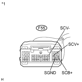
Text in Illustration *1 Front view of wire harness connector
(to Parking Assist ECU)
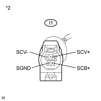
*2 Front view of wire harness connector
(to Outer Rear View Mirror Assembly RH)
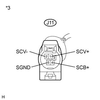
*3 Front view of wire harness connector
(to Outer Rear View Mirror Assembly LH)
Disconnect the J11 connector from the outer rear view mirror assembly LH.
-
Measure the resistance according to the value(s) in the table below.
Standard Resistance Tester Connection Condition Specified Condition F55-15 (SCV-) - J11-2 (SCV-) Always Below 1 Ω F55-16 (SCV+) - J11-1 (SCV+) Always Below 1 Ω F55-17 (SGND) - J11-5 (SGND) Always Below 1 Ω F55-18 (SCB+) - J11-4 (SCB+) Always Below 1 Ω F55-15 (SCV-) - Body ground Always 10 kΩ or higher F55-16 (SCV+) - Body ground Always 10 kΩ or higher F55-17 (SGND) - Body ground Always 10 kΩ or higher F55-18 (SCB+) - Body ground Always 10 kΩ or higher
-
NG 
REPAIR OR REPLACE HARNESS OR CONNECTOR
OK 
-
-
CHECK PARKING ASSIST ECU (SCV-, SGND)
-
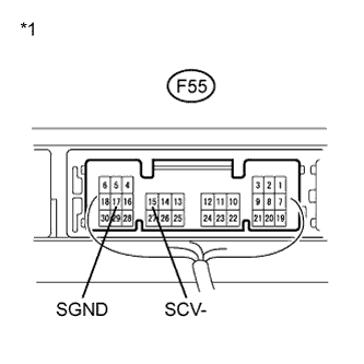
Text in Illustration *1 Component with harness connected
(Parking Assist ECU)
Reconnect the F55 connector to the parking assist ECU.
-
Measure the resistance according to the value(s) in the table below.
Standard Resistance Tester Connection Condition Specified Condition F55-15 (SCV-) - Body ground Always Below 1 Ω F55-17 (SGND) - Body ground Always Below 1 Ω
NG
REPLACE PARKING ASSIST ECU Click here
OK
-
-
CHECK OUTER REAR VIEW MIRROR ASSEMBLY (SCB+, SGND)
-
for LHD:
-
Disconnect the I1 connector from the outer rear view mirror assembly RH.
-
Measure the voltage according to the value(s) in the table below.
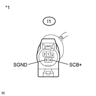
Standard Voltage Tester Connection Condition Specified Condition I1-5 (SGND) - I1-4 (SCB+) Power switch on (IG)
Side monitor main switch on
5.8 to 7.0 V
-
-
for RHD:
-
Disconnect the J11 connector from the outer rear view mirror assembly LH.
-

Text in Illustration *1 Front view of wire harness connector
(to Outer Rear View Mirror Assembly RH)
*2 Front view of wire harness connector
(to Outer Rear View Mirror Assembly LH)
Measure the voltage according to the value(s) in the table below.
Standard Voltage Tester Connection Condition Specified Condition J11-5 (SGND) - J11-4 (SCB+) Power switch on (IG)
Side monitor main switch on
5.8 to 7.0 V
-
NG
REPLACE PARKING ASSIST ECU Click here
OK
-
-
CHECK PARKING ASSIST ECU (SCV+, GND1)
-
Reconnect the I1 or J11 connector to the outer rear view mirror assembly (passenger side).
-
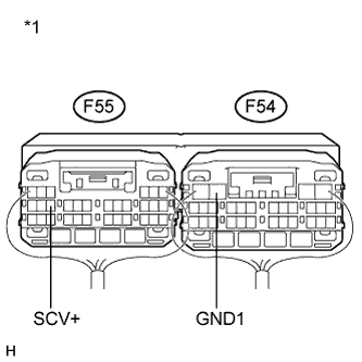
Reconnect the F54 and F55 connectors to the parking assist ECU.
-
Text in Illustration *1 Component with harness connected
(Parking Assist ECU)
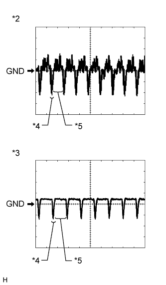
*2 Waveform 1 (under normal conditions) *3 Waveform 2 (camera lens is covered, blacking out the screen) *4 Synchronized Signal *5 Video Waveform Check the waveform of the side television camera assembly using an oscilloscope.
Tech Tips
A waterproof connector is used for the side television camera assembly. Therefore, inspect the waveform at the parking assist ECU with the connector connected.
OK Waveform is as shown in the illustration. Item Content Terminal No. (Symbol) F55-16 (SCV+) - F54-3 (GND1) Tool Setting 200 mV/DIV., 50 μsec./DIV. Condition Power switch on (IG), side monitor main switch on Tech Tips
The video waveform changes according to the image sent by the side television camera assembly.
NG 
REPLACE SIDE TELEVISION CAMERA ASSEMBLY Click here
OK 
PROCEED TO NEXT SUSPECTED AREA SHOWN IN PROBLEM SYMPTOMS TABLE Click here
-
-
REPLACE SIDE TELEVISION CAMERA ASSEMBLY
-
Replace the side television camera assembly with the new or normally functioning one Click here.
NEXT
-
-
CONFIRM SYMPTOMS
-
Check if the same malfunction recurs when the side monitor screen is displayed.
Result Result Proceed to Malfunction does not reoccur
(returns to normal)
A Malfunction reoccurs B
B
REPLACE OUTER REAR VIEW MIRROR ASSEMBLY Click here
A
END
-