SIDE MONITOR SYSTEM, Diagnostic DTC:C1684

| DTC Code | DTC Name |
|---|---|
| C1684 | Side Camera Current Malfunction |
DESCRIPTION
This DTC is stored if the parking assist ECU judges as a result of its self check that there is a problem with the current supplied to the side television camera assembly connected to the parking assist ECU.
| DTC No. | DTC Detection Condition | Trouble Area |
|---|---|---|
| C1684 | Side Camera Current Malfunction |
|
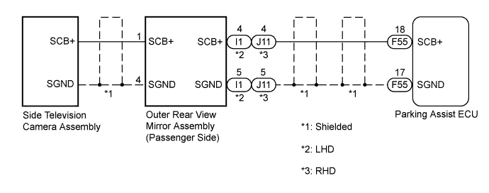
WIRING DIAGRAM
INSPECTION PROCEDURE
Note
-
When "System initializing" is displayed on the multi-display after the cable is disconnected from the negative (-) battery terminal, correct the steering angle neutral point Click here.
-
Depending on the parts that are replaced or operations that are performed during vehicle inspection or maintenance, calibration of other systems as well as the side monitor system may be needed Click here.
PROCEDURE
-
CHECK HARNESS AND CONNECTOR (PARKING ASSIST ECU - OUTER REAR VIEW MIRROR ASSEMBLY)
-
Disconnect the F55 connector from the parking assist ECU.
-
for LHD:
-
Disconnect the I1 connector from the outer rear view mirror assembly RH.
-
Measure the resistance according to the value(s) in the table below.
Standard Resistance Tester Connection Condition Specified Condition F55-17 (SGND) - I1-5 (SGND) Always Below 1 Ω F55-18 (SCB+) - I1-4 (SCB+) Always Below 1 Ω F55-17 (SGND) - Body ground Always 10 kΩ or higher F55-18 (SCB+) - Body ground Always 10 kΩ or higher
-
-
for RHD:
-
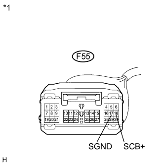
Text in Illustration *1 Front view of wire harness connector
(to Parking Assist ECU)
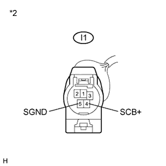
*2 Front view of wire harness connector
(to Outer Rear View Mirror Assembly RH)
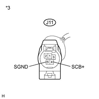
*3 Front view of wire harness connector
(to Outer Rear View Mirror Assembly LH)
Disconnect the J11 connector from the outer rear view mirror assembly LH.
-
Measure the resistance according to the value(s) in the table below.
Standard Resistance Tester Connection Condition Specified Condition F55-17 (SGND) - J11-5 (SGND) Always Below 1 Ω F55-18 (SCB+) - J11-4 (SCB+) Always Below 1 Ω F55-17 (SGND) - Body ground Always 10 kΩ or higher F55-18 (SCB+) - Body ground Always 10 kΩ or higher
-
NG 
REPAIR OR REPLACE HARNESS OR CONNECTOR
OK 
-
-
CHECK OUTER REAR VIEW MIRROR ASSEMBLY (SCB+, SGND)
-
for LHD:
-
Disconnect the I1 connector from the outer rear view mirror assembly RH.
-
Measure the voltage according to the value(s) in the table below.
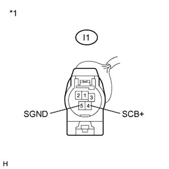
Standard Voltage Tester Connection Condition Specified Condition I1-5 (SGND) - I1-4 (SCB+) Power switch on (IG)
Side monitor main switch on
5.8 to 7.0 V
-
-
for RHD:
-
Disconnect the J11 connector from the outer rear view mirror assembly LH.
-

Text in Illustration *1 Front view of wire harness connector
(to Outer Rear View Mirror Assembly RH)
*2 Front view of wire harness connector
(to Outer Rear View Mirror Assembly LH)
Measure the voltage according to the value(s) in the table below.
Standard Voltage Tester Connection Condition Specified Condition J11-5 (SGND) - J11-4 (SCB+) Power switch on (IG)
Side monitor main switch on
5.8 to 7.0 V
-
NG
REPLACE PARKING ASSIST ECU Click here
OK
-
-
REPLACE SIDE TELEVISION CAMERA ASSEMBLY
-
Replace the side television camera assembly with a new or normally functioning one Click here.
NEXT
-
-
CHECK DTC OUTPUT
-
Clear the DTCs Click here.
-
Check for DTCs Click here.
Result Result Proceed to DTC C1684 is output A No DTC is output B
B
END
A 
REPLACE OUTER REAR VIEW MIRROR ASSEMBLY Click here
-